Introductory Circuit Analysis (13th Edition)
13th Edition
ISBN: 9780133923605
Author: Robert L. Boylestad
Publisher: PEARSON
expand_more
expand_more
format_list_bulleted
Question

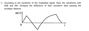
Transcribed Image Text:2. According to the waveform of the modulated signal. Draw the waveforms with
DSB and AM. Compare the difference of their waveform after passing the
envelope detector.
m(t) |
Expert Solution
This question has been solved!
Explore an expertly crafted, step-by-step solution for a thorough understanding of key concepts.
Step by stepSolved in 3 steps with 6 images

Knowledge Booster
Learn more about
Need a deep-dive on the concept behind this application? Look no further. Learn more about this topic, electrical-engineering and related others by exploring similar questions and additional content below.Similar questions
- The average value of a full-wave rectified voltage with a peak value of 75 Vis a. 53 V b. 47.8 V C. 37.5 V O d. 23.9 Varrow_forwardThe maximum peak-to-peak value of an AM wave is 120 V. The peak-to-peak value of the modulating signal is 20 V. Calculate the percentage of modulation 20 % 12% 5% 10% 0.0.arrow_forwardShow complete solutionarrow_forward
- You have a complex waveform made up of a 500 Hz signal with an 8Pa peak amplitudeand 0 deg starting phase and a 1000 Hz signal with a 2Pa peak amplitude and 90degstarting phase.a.What is the amplitude of the complex waveform at 15ms?arrow_forwardIf we use 1μF and 4.7μF capacitors in both Halfwave and Full wave rectifiers. Which one of the Capacitor will act as a better filter?arrow_forwardIn electronics, a clipper is a circuit designed to prevent a signal from exceeding a predetermined reference voltage level. A clipper does not distort the remaining part of the applied waveform. Clipping circuits are used to select, for purposes of transmission, that part of a signal waveform which lies above or below the predetermined reference voltage level. A biased clipper comes in handy when a small portion of positive or negative half cycles of the signal voltage is to be removed. ... Thus a biased negative clipper removes input voltage when the input signal voltage becomes greater than the battery voltage. QUESTION: Where do we exactly need to use a clipper circuit? State at least 3 examples and why it's needed on that application or device.arrow_forward
arrow_back_ios
arrow_forward_ios
Recommended textbooks for you
 Introductory Circuit Analysis (13th Edition)Electrical EngineeringISBN:9780133923605Author:Robert L. BoylestadPublisher:PEARSON
 Delmar's Standard Textbook Of ElectricityElectrical EngineeringISBN:9781337900348Author:Stephen L. HermanPublisher:Cengage Learning
 Programmable Logic ControllersElectrical EngineeringISBN:9780073373843Author:Frank D. PetruzellaPublisher:McGraw-Hill Education
 Fundamentals of Electric CircuitsElectrical EngineeringISBN:9780078028229Author:Charles K Alexander, Matthew SadikuPublisher:McGraw-Hill Education
 Electric Circuits. (11th Edition)Electrical EngineeringISBN:9780134746968Author:James W. Nilsson, Susan RiedelPublisher:PEARSON
 Engineering ElectromagneticsElectrical EngineeringISBN:9780078028151Author:Hayt, William H. (william Hart), Jr, BUCK, John A.Publisher:Mcgraw-hill Education,

Introductory Circuit Analysis (13th Edition)
Electrical Engineering
ISBN:9780133923605
Author:Robert L. Boylestad
Publisher:PEARSON

Delmar's Standard Textbook Of Electricity
Electrical Engineering
ISBN:9781337900348
Author:Stephen L. Herman
Publisher:Cengage Learning

Programmable Logic Controllers
Electrical Engineering
ISBN:9780073373843
Author:Frank D. Petruzella
Publisher:McGraw-Hill Education

Fundamentals of Electric Circuits
Electrical Engineering
ISBN:9780078028229
Author:Charles K Alexander, Matthew Sadiku
Publisher:McGraw-Hill Education

Electric Circuits. (11th Edition)
Electrical Engineering
ISBN:9780134746968
Author:James W. Nilsson, Susan Riedel
Publisher:PEARSON

Engineering Electromagnetics
Electrical Engineering
ISBN:9780078028151
Author:Hayt, William H. (william Hart), Jr, BUCK, John A.
Publisher:Mcgraw-hill Education,