
Elements Of Electromagnetics
7th Edition
ISBN: 9780190698614
Author: Sadiku, Matthew N. O.
Publisher: Oxford University Press
expand_more
expand_more
format_list_bulleted
Related questions
Question
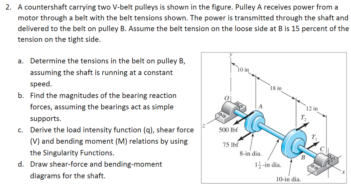

Transcribed Image Text:2. A countershaft carrying two V-belt pulleys is shown in the figure. Pulley A receives power from a
motor through a belt with the belt tensions shown. The power is transmitted through the shaft and
delivered to the belt on pulley B. Assume the belt tension on the loose side at B is 15 percent of the
tension on the tight side.
a. Determine the tensions in the belt on pulley B,
10 in
assuming the shaft is running at a constant
speed.
18 in
b. Find the magnitudes of the bearing reaction
forces, assuming the bearings act as simple
12 in
supports.
T2
C.
Derive the load intensity function (q), shear force
500 lbf
(V) and bending moment (M) relations by using
75 lbf
the Singularity Functions.
8-in dia.
В
d. Draw shear-force and bending-moment
1--in dia.
diagrams for the shaft.
10-in dia.
Expert Solution
This question has been solved!
Explore an expertly crafted, step-by-step solution for a thorough understanding of key concepts.

This is a popular solution

Trending nowThis is a popular solution!

Step by stepSolved in 3 steps with 4 images

Knowledge Booster

Similar questions
- For two existing torques, what third force at a given distance from the pivot will balance them? Imagine a meter stick set up as in the figure. It hangs from a central bracket, and two hanging masses can hang from it from each of their brackets. At a third location, a force probe can either pull up or pull down on the stick, depending on what is needed to balance the stick. The mass of the meter stick is 120 g. sketch the situation (drawing r1, r2, r3, F1, F2, and F3) and determine the magnitude (value) and direction (+ or -) of each torque. Don't include the mass of a bracket that would hold the hanging mass in place; assume the mass listed is the entire mass hanging at that point. For each trial, use the principle of equilibrium (where the sum of torques is zero) to calculate the third, unknown force acting at x3arrow_forwardFor two existing torques, what third force at a given distance from the pivot will balance them? Imagine a meter stick set up as in the figure. It hangs from a central bracket, and two hanging masses can hang from it from each of their brackets. At a third location, a force probe can either pull up or pull down on the stick, depending on what is needed to balance the stick. The mass of the meter stick is 120 g. sketch the situation (drawing r1, r2, r3, F1, F2, and F3) and determine the magnitude (value) and direction (+ or -) of each torque. Don't include the mass of a bracket that would hold the hanging mass in place; assume the mass listed is the entire mass hanging at that point. For each trial, use the principle of equilibrium (where the sum of torques is zero) to calculate the third, unknown force acting at x3arrow_forwardSolve it.arrow_forward
- Force between A and B: 200lb Angle on D: 35 deg Angle on C: 50 degarrow_forwardThe operation of the exhaust and intake valves in an automobile engine consists of cam C, pushrod DE, rocker arm EFG which is hinged at F and on a spring , and valve V. If the compression on the spring is 20 mm when the valve is open, as indicated in the figure, determine the normal force acting on the lobe of the cam at C. Assume that the cam and the bearings at H, I, and J are smooth. The spring has a stiffness of 300N/m. draw the free body diagramarrow_forwardA countershaft carrying two V-belt pulleys is shown in the figure. Pulley A receives power from amotor through a belt with the belt tensions shown. The power is transmitted through the shaft anddelivered to the belt on pulley B. Assume the belt tension on the loose side at B is 15 percent ofthe tension on the tight side.(a) Determine the tensions in the belt on pulley B, assuming the shaft is running at a constantspeed.(b) Find the magnitudes of the bearing reaction forces, assuming the bearings act as simplesupports.(c) Draw shear-force and bending-moment diagrams for the shaft. If needed, make one set for thehorizontal plane and another set for the vertical plane.(d) At the point of maximum bending moment, determine the bending stress and the torsionalshear stress.(e) At the point of maximum bending moment, determine the principal stresses and themaximum shear stress.arrow_forward
arrow_back_ios
arrow_forward_ios
Recommended textbooks for you
- Elements Of ElectromagneticsMechanical EngineeringISBN:9780190698614Author:Sadiku, Matthew N. O.Publisher:Oxford University Press
 Mechanics of Materials (10th Edition)Mechanical EngineeringISBN:9780134319650Author:Russell C. HibbelerPublisher:PEARSON
 Thermodynamics: An Engineering ApproachMechanical EngineeringISBN:9781259822674Author:Yunus A. Cengel Dr., Michael A. BolesPublisher:McGraw-Hill Education
  Control Systems EngineeringMechanical EngineeringISBN:9781118170519Author:Norman S. NisePublisher:WILEY
 Mechanics of Materials (MindTap Course List)Mechanical EngineeringISBN:9781337093347Author:Barry J. Goodno, James M. GerePublisher:Cengage Learning
 Engineering Mechanics: StaticsMechanical EngineeringISBN:9781118807330Author:James L. Meriam, L. G. Kraige, J. N. BoltonPublisher:WILEY
Elements Of Electromagnetics
Mechanical Engineering
ISBN:9780190698614
Author:Sadiku, Matthew N. O.
Publisher:Oxford University Press
Mechanics of Materials (10th Edition)
Mechanical Engineering
ISBN:9780134319650
Author:Russell C. Hibbeler
Publisher:PEARSON
Thermodynamics: An Engineering Approach
Mechanical Engineering
ISBN:9781259822674
Author:Yunus A. Cengel Dr., Michael A. Boles
Publisher:McGraw-Hill Education
Control Systems Engineering
Mechanical Engineering
ISBN:9781118170519
Author:Norman S. Nise
Publisher:WILEY
Mechanics of Materials (MindTap Course List)
Mechanical Engineering
ISBN:9781337093347
Author:Barry J. Goodno, James M. Gere
Publisher:Cengage Learning
Engineering Mechanics: Statics
Mechanical Engineering
ISBN:9781118807330
Author:James L. Meriam, L. G. Kraige, J. N. Bolton
Publisher:WILEY