
Structural Analysis
6th Edition
ISBN: 9781337630931
Author: KASSIMALI, Aslam.
Publisher: Cengage,
expand_more
expand_more
format_list_bulleted
Related questions
Concept explainers
Question
Determine the position of the centroid for the following figures shown below and compute the moment of inertia with respect to the centroidal X and Y axes.
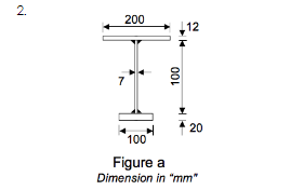

Transcribed Image Text:2.
200
7
100
►
12
20
100
Figure a
Dimension in "mm"
Expert Solution
This question has been solved!
Explore an expertly crafted, step-by-step solution for a thorough understanding of key concepts.

Step by stepSolved in 2 steps with 2 images

Knowledge Booster


Learn more about
Need a deep-dive on the concept behind this application? Look no further. Learn more about this topic, civil-engineering and related others by exploring similar questions and additional content below.Similar questions
- A trapezoid is shown in the figure. 6 6 6 6 6 Compute the area of the trapezoid. 2 Compute the centroid of the trapezoid. 3 Compute the centroidal moment of inertia of the trapezoid.arrow_forwardThe force along rod AC is 1000 N. a) Express the force on rod AC, FAC, as a Cartesian Vector.arrow_forwardThe moments of inertia Ixx, Iyy and Ixy with respect to the xy reference frame shownin Figurearrow_forward
- Solve NA and NB, I got NB correct and NA wrong. Please show all work.arrow_forwardExample: Resolve the horizontal 600 N force in shown into and components acting along the u and v axes determine the magnitudes of these components. F 30° 130 600 lbarrow_forward1. Use the force method to calculate the redundant reaction of the indeterminate beam. E is constant, I varies as shown below. (40 points – Suggested time 45 minutes) 4 k/ft 5 k 50 k.ft 10 ft 5 ft 5 ft 5 ft 21arrow_forward
- Consider the frame as shown in figure. Assume A is a pin jointed support and C is a roller jointed support. The maximum bending moment occurs at a point R, the distance of R from A measured vertically from A is 40 kN/m 4 m 80 kN 2 m 2m 3 marrow_forwardA structure consists of two thin rectangular plates having the same dimensions (shown in figure) and same mass, m = 8 kg esch. The two plates are welded together to form a rigid body that may rotate in the plane. Determine, for this rigid body, the moment of inertia ly about the fixed point P. P is frisedarrow_forwardIn the beam depicted above, ?A is a fixed support. The magnitude of ?=365?/?W=365N/m, ?=60?P=60N and all lengths denoted by ?=1.5?a=1.5m. The system is in equilibrium. Using the given sign convention, answer the following questions. a) Calculate the vertical component of the external reaction at ?A in ???????Newtons. b) Calculate the horizontal component of the external reaction at ?A in ???????Newtons. c) Calculate the moment component of the external reaction at ?A in ??????Newton ??????metres. d) Calculate the shear force at point ?B in ???????Newtons. e) Calculate the bending moment at ?B in ??????Newton ??????metres. f) Calculate the shear force at point ?D in ???????Newtons. g) Calculate the bending moment (absolute value) at ?D in ??????Newton ??????metres. h) Calculate the shear force at point ?E in ???????Newtons. i) Calculate the bending moment at ?E in ??????Newton ??????metres. j) Calculate the shear force at point ?H in…arrow_forward
- 150 mm 60 mn 300 nm 000 m 50 mm 5 m B 25 kNm 5 m 10 KN A beam is created by nailing 3 planks together with 2 rows of nails as shown above. The beam exhibits a pin support at A and is suspended by a cable at B. A concentrated load of 10 kN is applied at the free end while a moment of 25 kNm is applied at location B. a) Determine the second moment of area (I) of the cross-section b) Draw the free body diagram, shear force diagram, and bending moment diagram of the beam c) For the maximum shear force on your SFD, determine the maximum and minimum shear stresses at the interface between the horizontal and vertical planks d) For the maximum shear force on your SFD, Determine the shear stress at the neutral axisarrow_forwardShown below are 4 different rigid bodies, supported in different ways. For each of the rigid bodies, with proper free body diagrams, please determine all the support reactions. Value of the applied forces is F = 100 N, P = 200 N and L = 3 m. a. In figure a, support is a pin at A and a roller at D. Pin at A resists translation in the horizontal and vertical direction, and roller at D only resists translation in the vertical direction. b. In figure b, support at A is a pin it similar to part a of the problem), and support at D is a roller on an incline: note that here, the roller support reaction will be normal to the incline. c. In figure c, support at A is a roller, and support at D prevents translation in the horizontal direction, and also prevents rotation. So, there will be two support reactions at D. Think of what they may be? d. In figure d, support at A is a cantilevered end. B 30° (a) (b) |F | F |P (c) (d) /3arrow_forwardA beam supported by three identical springs at points A,B,C (see figure). Given that flexural of rigidity of the beam, EI= 2.029X10¹¹ N.mm2 ; spring constant,k = 1471.5N/mm, w=116N/mm All dimensions are in mm. 1. What is the reaction for at point A,B and C? 2. What is the deflection at point B? 3. Please draw shear-force and bending moment diagram.arrow_forward
arrow_back_ios
SEE MORE QUESTIONS
arrow_forward_ios
Recommended textbooks for you
 Structural Analysis (10th Edition)Civil EngineeringISBN:9780134610672Author:Russell C. HibbelerPublisher:PEARSON
 Principles of Foundation Engineering (MindTap Cou...Civil EngineeringISBN:9781337705028Author:Braja M. Das, Nagaratnam SivakuganPublisher:Cengage Learning
 Fundamentals of Structural AnalysisCivil EngineeringISBN:9780073398006Author:Kenneth M. Leet Emeritus, Chia-Ming Uang, Joel LanningPublisher:McGraw-Hill Education
 Traffic and Highway EngineeringCivil EngineeringISBN:9781305156241Author:Garber, Nicholas J.Publisher:Cengage Learning
Structural Analysis (10th Edition)
Civil Engineering
ISBN:9780134610672
Author:Russell C. Hibbeler
Publisher:PEARSON
Principles of Foundation Engineering (MindTap Cou...
Civil Engineering
ISBN:9781337705028
Author:Braja M. Das, Nagaratnam Sivakugan
Publisher:Cengage Learning
Fundamentals of Structural Analysis
Civil Engineering
ISBN:9780073398006
Author:Kenneth M. Leet Emeritus, Chia-Ming Uang, Joel Lanning
Publisher:McGraw-Hill Education
Traffic and Highway Engineering
Civil Engineering
ISBN:9781305156241
Author:Garber, Nicholas J.
Publisher:Cengage Learning