
Introductory Circuit Analysis (13th Edition)
13th Edition
ISBN: 9780133923605
Author: Robert L. Boylestad
Publisher: PEARSON
expand_more
expand_more
format_list_bulleted
Related questions
Concept explainers
Question
thumb_up100%
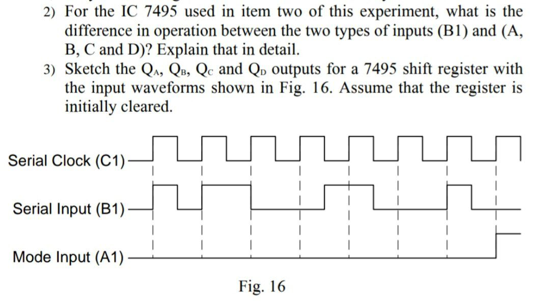

Transcribed Image Text:2) For the IC 7495 used in item two of this experiment, what is the
difference in operation between the two types of inputs (B1) and (A,
B, C and D)? Explain that in detail.
3) Sketch the Q₁, QB, Qc and QD outputs for a 7495 shift register with
the input waveforms shown in Fig. 16. Assume that the register is
initially cleared.
Serial Clock (C1)
Serial Input (B1)
Mode Input (A1)
Fig. 16
Expert Solution
This question has been solved!
Explore an expertly crafted, step-by-step solution for a thorough understanding of key concepts.

Step by stepSolved in 2 steps

Knowledge Booster


Learn more about
Need a deep-dive on the concept behind this application? Look no further. Learn more about this topic, electrical-engineering and related others by exploring similar questions and additional content below.Similar questions
- Consider the LSFR with 3 shift registers. The initial conditions are s2 = 1, s1=0, s0 =0, and the feedback is given by P2=1, P1=0, P0=1.Draw a table showing the output of the LSFR. What is the maximum sequence length before repeating?arrow_forwardA 5-bit ADC has the following reference values Vref = -2V and 12 V. What is the voltage represented by the output sequence 01010?arrow_forward2. The following circuit represents a 3-bitlinear-feedback shift register (LFSR). Find the counting sequence (Q.Q1Q2) by loading the pattern 010 (via rorir3) into the LFSR by L = 1, and then enabling the register to count by L = 0. ro D Q D Q D Q Q Q L Clockarrow_forward
- Example 2-5. A 15-kVA, 2300/230-V transformer is to be tested to determine its excitation branch components, its series impedances, and its voltage regulation. The fol- lowing test data have been taken from the transformer: Open-circuit test (low voltage side) Voc 230 V loc= 2.1 A Voc = 50 w Short-circuit test (high voltage side) Vsc = 47 V sc = 6.0 A Psc 160 W Find the equivalent circuit parameters Xp,Rp,Xs, Rs, Xm,Rcarrow_forwardWhich of the following statements are true about relative effect of quantization error values like the one computed in the previous problem? O The relative effect of quantization error depends on the voltage value currently being read in. O Relative effect of quantization error will seldom be a concern with strain gauge outputs because the output voltage is typically large. V A relative effect of quantization error value of around 100% means that the quantization error is as large as the signal itself. O A relative effect of quantization error value of around 50% means that the read-in signal will be quite noisy.arrow_forwardGiven a 5-bit ADC with the following reference values Vref= -2V and 12V, what is the voltage represented by the output sequence 01010?arrow_forward
- 1What will be the state of a MOD64 counter after 90 input pulses if the starting state=000000?A.100100B.011010C.010110D.011100 2.A MOD 32 counter is holding the count 101112. What will the count be after 31 clock pulses?A.10100B.10010C.10000D.10110arrow_forwardQ2 - Pseudo-Random Number Generator a) The following circuit is a pseudo-random number generator which uses linear feedback shift registers to produce a stream of outputs. The XOR tap at index '1' is responsible for generating this sequence of outputs. Fill in the table for the outputs of the 4 registers after each clock cycle. The initial output state is already provided in the first row. You can stop when the output starts to repeat and just say that it is repeating. QO Q1 Q2 Q3 ID ClockEdge # Q3 Q2 Q1 QO 1 1 2 3 7 10 11 12 13 14 00arrow_forwardHow do I solve the problem given below?arrow_forward
- What is the maximum quantization error of an ideal 4-bit quantizer with a signed input signal having amplitude ±6? Answer should be with 4 decimal places.arrow_forwardA4 bit shift register, which shifts one bit to the right at every clock pulse, is initialized to values "1000" for Q0Q1Q2Q3. The 'D' input is derived from QO,Q2 and Q3 through two XOR gates as shown in below Fig. (a) How many clock pulses are needed for pattern 1000 reappears on Q0Q1Q2Q3 and write down logic table? (b) To what values should the shift register be initialized so that the pattern "1001" occurs after the first clock pulse? 88 9 Q Darrow_forwardAnswer the D, E and F partarrow_forward
arrow_back_ios
SEE MORE QUESTIONS
arrow_forward_ios
Recommended textbooks for you
- Introductory Circuit Analysis (13th Edition)Electrical EngineeringISBN:9780133923605Author:Robert L. BoylestadPublisher:PEARSON
 Delmar's Standard Textbook Of ElectricityElectrical EngineeringISBN:9781337900348Author:Stephen L. HermanPublisher:Cengage Learning
 Programmable Logic ControllersElectrical EngineeringISBN:9780073373843Author:Frank D. PetruzellaPublisher:McGraw-Hill Education
  Fundamentals of Electric CircuitsElectrical EngineeringISBN:9780078028229Author:Charles K Alexander, Matthew SadikuPublisher:McGraw-Hill Education
 Electric Circuits. (11th Edition)Electrical EngineeringISBN:9780134746968Author:James W. Nilsson, Susan RiedelPublisher:PEARSON
 Engineering ElectromagneticsElectrical EngineeringISBN:9780078028151Author:Hayt, William H. (william Hart), Jr, BUCK, John A.Publisher:Mcgraw-hill Education,
Introductory Circuit Analysis (13th Edition)
Electrical Engineering
ISBN:9780133923605
Author:Robert L. Boylestad
Publisher:PEARSON
Delmar's Standard Textbook Of Electricity
Electrical Engineering
ISBN:9781337900348
Author:Stephen L. Herman
Publisher:Cengage Learning
Programmable Logic Controllers
Electrical Engineering
ISBN:9780073373843
Author:Frank D. Petruzella
Publisher:McGraw-Hill Education
Fundamentals of Electric Circuits
Electrical Engineering
ISBN:9780078028229
Author:Charles K Alexander, Matthew Sadiku
Publisher:McGraw-Hill Education
Electric Circuits. (11th Edition)
Electrical Engineering
ISBN:9780134746968
Author:James W. Nilsson, Susan Riedel
Publisher:PEARSON
Engineering Electromagnetics
Electrical Engineering
ISBN:9780078028151
Author:Hayt, William H. (william Hart), Jr, BUCK, John A.
Publisher:Mcgraw-hill Education,