
Introductory Circuit Analysis (13th Edition)
13th Edition
ISBN: 9780133923605
Author: Robert L. Boylestad
Publisher: PEARSON
expand_more
expand_more
format_list_bulleted
Related questions
Question
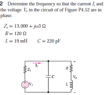

Transcribed Image Text:2 Determine the frequency so that the current I, and
the voltage V, in the circuit of of Figure P4.52 are in
phase.
Z, = 13,000 + jw3 N
R= 120 2
L = 19 mH
C = 220 pF
R
V.
L.
Expert Solution
This question has been solved!
Explore an expertly crafted, step-by-step solution for a thorough understanding of key concepts.

This is a popular solution

Trending nowThis is a popular solution!

Step by stepSolved in 4 steps with 4 images

Knowledge Booster

Similar questions
- 7 Determine the equivalent impedance in the circuit shown in Figure P4.47: л v,(t) = 7 cos (3,000t +) R = 2.3 k2 R2 = 1.1 k2 %3D L = 190 mH C = 55 nF R1arrow_forwardQUESTION 4 For the circuit in Figure Q4a, draw the phasor domain equivalent circuit. Given that Is(t)=2 cos 1000t A. Then determine the steady state voltage Vs(t). a) b) + i) ii) Vs(t) ZT 992 m 12mH For the circuit in Figure Q4b, determine; Vs = 85 215° Vrms Ve Figure Q4a The phasor current, I, and the phasor voltage, Vx The real power and the reactive power of the source. 0.25mF 10 Ω – j30 Ω 2 - ww 20 Ω j10 Ω -j30 2 1092 Figure Q4b 20 Ω j20 Ω 1,(1) lmFarrow_forwardOkay for Determine the mathematical expression for the voltage vC and the current iC for the discharge phase. I got Vc = 8e-t/0.2s V and iC = -4e-t/0.2mA But I need help with the last question Plot the waveforms of vC and iC for a period of time extending from 0to 2 s from when the switch was thrown into position 1.arrow_forward
- For the circuit shown in Figure (4.a): i) a) Find the voltage across the capacitor in polar form. ii) Draw the phasor diagram relationship of Vc and Vs. iii) Is this circuit pre-dominantly inductive or capacitive? Why? R1=1kN X1 = 5000 Vs= 50 0 Xe = 5000 R2=1knarrow_forward9 Inthe circuit of Figure P4.49, i,(1) = 1, cos (wt +E I, = 13 mA C = 0.5 µF w = 1,000 rad/s a. State, using phasor notation, the source current. b. Determine the impedance of the capacitor. c. Using phasor notation only and showing all work, determine the voltage across the capacitor, including its polarity.arrow_forwardP4.26. The circuit shown in Figure P4.26 is operating in steady state. Determine the values of i L, vx, and v C. 3 k 3 kl 15 mA 7 mH I uF 5 mH 20 V Figure P4.26arrow_forward
- Solve the collector current (Ic) of Figure 611. VC T18V R2 3.9kQ R1 Vc = 8V 680ka Figure 611arrow_forward5 Using phasor techniques, solve for the voltage v in the circuit shown in Figure P4.55. i(t) = 10 cos 2t A 303 3 Hg 1/3 F v(t)arrow_forwardHow is part I Zeq=200-j30 and part II cApacitivearrow_forward
- Q4. The equation relating the current in a circuit with time is i=282.1 sin377t, where the current is measured in amperes and the time in seconds. Find the values of: The r.m.s current The frequency The instantenous value of the current when t=2.0msarrow_forward3 Determine the equivalent impedance in the circuit shown in Figure P4.47: v,(1) = 636 cos (3,000t + ) v R2 = 22 k2 C = 6.8 nF 12. R = 3.3 k2 L = 1.90 Harrow_forward4.10 A dc-dc converter is connected to a 100 V d.c. source to supply an inductive load having 40 mH in series with 5 2 resistance. FWD is placed across the load. Load current varies between two limits of 10 A and 12 A. (a) Find the time ratio (duty cycle) and the frequency of the chopper. (b) Find the equivalent Thevenin resistance across the source and determine the average source current.arrow_forward
arrow_back_ios
SEE MORE QUESTIONS
arrow_forward_ios
Recommended textbooks for you
- Introductory Circuit Analysis (13th Edition)Electrical EngineeringISBN:9780133923605Author:Robert L. BoylestadPublisher:PEARSON
 Delmar's Standard Textbook Of ElectricityElectrical EngineeringISBN:9781337900348Author:Stephen L. HermanPublisher:Cengage Learning
 Programmable Logic ControllersElectrical EngineeringISBN:9780073373843Author:Frank D. PetruzellaPublisher:McGraw-Hill Education
  Fundamentals of Electric CircuitsElectrical EngineeringISBN:9780078028229Author:Charles K Alexander, Matthew SadikuPublisher:McGraw-Hill Education
 Electric Circuits. (11th Edition)Electrical EngineeringISBN:9780134746968Author:James W. Nilsson, Susan RiedelPublisher:PEARSON
 Engineering ElectromagneticsElectrical EngineeringISBN:9780078028151Author:Hayt, William H. (william Hart), Jr, BUCK, John A.Publisher:Mcgraw-hill Education,
Introductory Circuit Analysis (13th Edition)
Electrical Engineering
ISBN:9780133923605
Author:Robert L. Boylestad
Publisher:PEARSON
Delmar's Standard Textbook Of Electricity
Electrical Engineering
ISBN:9781337900348
Author:Stephen L. Herman
Publisher:Cengage Learning
Programmable Logic Controllers
Electrical Engineering
ISBN:9780073373843
Author:Frank D. Petruzella
Publisher:McGraw-Hill Education
Fundamentals of Electric Circuits
Electrical Engineering
ISBN:9780078028229
Author:Charles K Alexander, Matthew Sadiku
Publisher:McGraw-Hill Education
Electric Circuits. (11th Edition)
Electrical Engineering
ISBN:9780134746968
Author:James W. Nilsson, Susan Riedel
Publisher:PEARSON
Engineering Electromagnetics
Electrical Engineering
ISBN:9780078028151
Author:Hayt, William H. (william Hart), Jr, BUCK, John A.
Publisher:Mcgraw-hill Education,