1Ω 1Ω + F= v(t) + 10 cos t V (* 1 H ll
Q: Example 1: Sketch the root locus for the system shown in figure. R(s) + K(s + 3) C(s) s(s + 1)(s +…
A:
Q: Q1: For the circuit shown below, www 100 cos 21 V 2H 1H The coupling coefficient is -1 إجابتك The…
A:
Q: The R-C circuit shown below has an AC power supply with 150 Vrms / 50 Hz output. Moreover, R1=8kN,…
A: The total resistance of the circuit is Req=R1+R2=8K+10K=18KΩ The two capacitors are in series, then…
Q: If the roots of the characteristic equation are -1+j2, -1-j2,-3 then the system is O Unstable Stable…
A:
Q: In the circuit shown, i(t) = 10 sin 1.5t . Calculate the value of L such that v(t) = Vo sin 1.5t V.…
A:
Q: 2. A 33 kV, 50 Hz network has a capacitance to neutral of 1.0 μF per phase. Calculate the reactance…
A: inductance of arc supression coil coil L= 13 w2c where w is the frequency in rad / sec. c is…
Q: 1. Draw the root locus of the system given in the figure (K>0). 4(s+3) Kis 52+25+64 T>YIS) S+2
A: Given: The system is given as: To find: Draw the root locus for K>0.
Q: In a Transistorised Hartley oscillator, the two inductances are 2 mH and 20 mH while the frequency…
A: Given the value of the inductance is 2 mH and 20 mH. Consider the value of frequency is 930 kHz and…
Q: Determine the single circuit element for which the current and voltage in the interval 0 > 10³i > n…
A: Inductor is passive element that store energy in magnetic field. The voltage across inductor is…
Q: Question 2 Given A=e*a, +2 cos ya, +2 sin za, , find V• A at the origin.
A:
Q: The self inductance of two coils are 4mH and 9mH respectively. If the coefficient of coupling is…
A: Given data, Self inductance of two coils, L1=4 mHL2=9 mH Coefficient of coupling, k=0.5
Q: Determine the stability of the system having characteristic equation s^5 + s^4 + 2s^3 + 2s^2 + 3s +…
A: The given characteristic equation is: s5+s4+2s3+2s2+3s+5=0
Q: 1. For the circuit below, let v, = 2 sin(@t) and g, = 5 mS = 1/(0. 2 k2), and find v.(t). 9 k2 1 kQ…
A: We need to find output voltage for given circuit.
Q: 1. A coil of resistance 50 2 and inductance of 100 mH is connected in series with a capacitance of…
A: Voltage and current at different loads R-Load - There is no phase difference between voltage and…
Q: 2. A capacitor of 50 µF is connected in parallel with a coil that has a resistance of 20 Q and…
A:
Q: Find v.(t) using nodal analysis. 10 2 10 2 5 sin (1000 t) ( ↑ 302 50 µF 10 mH
A: The solution is given below
Q: The system described by y(n)=nx(n)+sin(x(n)) is * Dynamic system Static system Time invariant system…
A: Let us discuss different type of systems in order to solve this question as illustrated below.
Q: Block diagram of a system is giveo, below: Reference, R(s) Output, C(s) s +2s +2 s(s + 5s + 6) Σ…
A: In the circuit, the block diagram of the system is given. Draw the root locus plot of the system.…
Q: If F(s) = s 4+ 5s3+20s 2 + 40s + 50 , Investigate the stability of this system
A: F(s) = s4 + 5s3 +20s2 + 40s + 50 , Investigate the stability of this system?
Q: Determine the effective inductance of the series-connected coupled coils shown in Fig. 2H 3H 3H 2H…
A: Given a series connected coupled coil,
Q: - Find the DC steady state current i, and i,. 4 mH 1 mA (1 2 k2 1 µF 1 mH 1 kQ 6 V Answer: =i, = 4…
A:
Q: În the circuit shown below, Is(t) = 10/2 cos (104t + 30°) A, and RA = 12. 0.4mH V2 V V3 Is(t) RA…
A: The given circuit is:
Q: 3 A 40uF capacitor in series with a coil of resistance 8ohms and inductance 80mH is connected to a…
A: As per our company guidelines we are supposed to answer only first 3 subpart kindly repost the other…
Q: An AC generator whose emf is given by v(t) = 4 sin(1 x 10*)t (V), is connected to an RLC circuit for…
A: Solution- Given,v(t) = 4 sin(1*104)t (V)L=2mH C=4μFR=5Ω
Q: Electrical Engineering Question
A: Given: The given circuit is an integrator using Op-amp. The output is the integration version of the…
Q: t = 0 3 kΩ 6 kΩ i 5 kΩ 1.5i, vC :1 µF 10 V 4. Determine vc(0*), Ve(0*), the time constant, Ve(3ms).
A:
Q: B- Determine the maximum energy stored in the capacitor of the circuit shown and the energy…
A:
Q: 2.14 Prove the following: (а) а, X а, a, X as = cos o 3 - sin ф = sin & а, Х а, — сosф а, Х а, ay
A: According to the question, we need to prove
Q: 3. A coil of resistance 60N and inductance 318.4 mH is connected in parallel with a 15 µF capacitor…
A:
Q: For the circuit shown below with k 0.6, the value of the energy stored in the coupled coils at t-0…
A: In this question, We need to choose the correct options What is the stored energy in the coupled…
Q: Given the characteristic equation, s^7 + 4s^6 + s^5 + 3s^4 + 2s^3 + s^2 + 4s + 4 = 0. Justify the…
A: In this question , we will find system stability using routh criterion..
Q: Q) Consider the circuit shown in Fig.1. The input to the circuit is the voltage source v(t)=7.68cos…
A: Given Input voltage and output voltage.we need to determine capacitance. Please find the below…
Q: Exercise 2: Consider the following system, plot the root locus with all details and find the value…
A: “Since you have asked multiple questions, we will solve the first question for you. If you want any…
Q: Vs m 0.5 H M m 1 H 25 mF 12 www 5Ω
A:
Q: Given A=e"a, +2 cos ya, +2 sin za,, find V A at the origin.
A:
Q: 4. Find i, in the circuit given below if is = 5 cos(10t + 40°) A 30 0.2 H i, 0.1 F
A:
Q: Consider the circuit shown below. What is the equivalent impedance for maximum current? Assume the…
A: In this question, We need to determine the equivalent impedance for maximum current. We know…
Q: 4. For the following circuit, determine v (t) and i, (t) if i, (t) = 12 cos (1000t – 4°) A, v,1 (t)…
A: Given, is(t)=12 cos1000t-4° A,Vs1(t)=50 sin(1000t+20°) VVs2(t)=10 cos(1000t)…
Q: Determine the time-dependent current i (t) through the 2H- inductor. 2H 1.cos(2t)V 1/14 1/2
A:
Q: Problem (3) In the circuit shown, i(t) = 10 sin 1.5t . Calculate the value of L such that v(t) = Vo…
A: Voltage and current are in same phase .it is possible when load is a resistive (imaginary part in…
Q: A 6.36 μF capacitor is connected in parallel with a resistance of 500Ω and the combination is…
A: We are authorized to answer three subparts at a time, since you have not mentioned which part you…
Q: In the following circuit, If R, = 1N, then i, is: 10 2
A: The solution can be achieved as follows.
Q: Determine the Thevenin equivalent of the circuit in Fig. 10.27 as seen from the terminals a-b.…
A: The thevenin's equivalent circuit can be calculated by using the nodal analysis and the equivalent…
Q: 310 0.25 F t = 0 t = 0 0.5 H 5 V 6 V In the circuit shown below, switch action occurs at t = 0.…
A:
Q: Q2: For the circuit shown below, assuming Vin(t) = 0.2 sin(500tt): 1. What is the function of the…
A:
Q: 5Ω 10 Ω 20 Ω 12.5 μF Vs 2.5 mH The circuit above if vs(t) = 25 sin 4000r V. Find io(t) ? (+ I
A: Given: Vs(t)=25sin4000tso Vm=25 Vand ω=4000 rad/sec
Q: (1) Calculate i, (t) for t > 0, assuming the circuit is at steady state at t = 0-. (2) Plot i, (t)…
A:
Q: 1. A coil of resistance 50 2 and inductance of 100 mH is connected in series with a capacitance of…
A:
Q: Two parallel circuits comprise respectively (î) a coil of resistance 20 Nand inductance 0.07 H and…
A: Kirchoff's voltage and the current law is an important law in the electrical networks which is used…
Q: ١** series RLC, R= 1 ohm, C= 0.2 F, L = 0.4H, Vs(t) = 10 Cos ( 5t - 45) V, the value of the…
A:
(a) Calculate the total impedance of the circuit.
(b) Calculate the voltage of the capacitor (v(t)).
Can you help me with this?
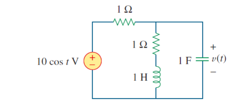
![1Ω
1Ω
+
10 cos t V
1F =
+v(t)
1 H
+
ll](/v2/_next/image?url=https%3A%2F%2Fcontent.bartleby.com%2Fqna-images%2Fquestion%2Fd6bbb3d8-19cf-486d-b77a-ef99218ca907%2F934b4411-1727-4fa4-846d-00c3f68533b1%2Fr7aan4_processed.png&w=3840&q=75)
![](/static/compass_v2/shared-icons/check-mark.png)
Step by step
Solved in 2 steps with 2 images
![Blurred answer](/static/compass_v2/solution-images/blurred-answer.jpg)
- Find: Ib, Ic, Vce, Vb, Vc, Vrb Vre, & Vrc Note: show your solutions no solution means wrong answers. C2 HE 1000μF Rb 560 ΚΩ VCC 12V Rc 2kQ Q1 C1 요 HE 1000μF 2SC1815 R1 2000Which ane oli the functions given below is a solton of the UL dy 2y dx None of These In y + 2 In x =c x²+c X+C 2What is the total equivalent (total) inductance Lr of this circuit? 000 30mH L2 R 000 60mH 1 kQ 10 V L3 100mH 000 500mH 43 mH 720 mH O 173 mH o 日 点四RUA 36% DE 40°F PriSc Impr. Écr. F12 F10 F11 F7 F8 F9 F4 F5 F6 * & 3 0 1/4 1/2 4. 5 6. 7 8 2 R Y K L
- 9 62 802 5 mH 一 80V 156 1oov o=t エ has been n positien it moves to position The Switeh n the civauit in for a log time. At +=0 b. Find reltl for t70.x=9 and write the solution like this 0,****Determine the value of 'w' in the figure such that the peak value of i(t) is 0.25 A. Use the VR2 + X², identities z = and - jxe - if needed. jwe (1) 100 ww v(t) = 25 cos wt V *0.002 F 6.67 5.02 10.2 None of the answers A Moving to another question will save this response. MacBook Pro 20 47 725 F2 F3 F4 #3 & 2$ 48 % 50 67 AL
- Find T 0.5 ms 40 92 www www 892 160 92 20 mH www47 Determine the power dissipated at R5. Rs = 100 N 300 N R1 100 N R4 R5 = 100 N %3D E + 24 V 300 N R4 R3 900 N 202.5mA 360mA 67.5mAProblem 2: Determine the voltages across the wo capacitors and the currents through the two inductors under dc conditions. 55 32H C1 =2pF R1 w 1000 R2 www 500 C2 HI 1μF R3 www 300 Den L2 5H R4 900
- Electrical Engineering 6/0° v j1 N V1 V2 1Ω 1 Ω -j1 N= 2/0° A find loFind the voltage across the capacitors in the given circuit under dc conditions, where R₁ = 67 Q and R₂ = 17 Q. 1092 R₁ www C₁ +51 - www 50 92 R₂ 60 V The voltage across the capacitors are v₁ = 1 + 22 HH C₂ V and v25 V.Please help me solve this using P=1/2 Re (E.H*)
![Delmar's Standard Textbook Of Electricity](https://www.bartleby.com/isbn_cover_images/9781337900348/9781337900348_smallCoverImage.jpg)