Introductory Circuit Analysis (13th Edition)
13th Edition
ISBN: 9780133923605
Author: Robert L. Boylestad
Publisher: PEARSON
expand_more
expand_more
format_list_bulleted
Concept explainers
Question
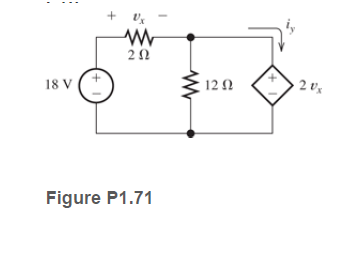
Determine the value of v x and i y in the circuit shown in Figure P1.71.

Transcribed Image Text:18 V
12 N
2 v's
Figure P1.71
Expert Solution
This question has been solved!
Explore an expertly crafted, step-by-step solution for a thorough understanding of key concepts.
This is a popular solution
Trending nowThis is a popular solution!
Step by stepSolved in 2 steps with 3 images

Knowledge Booster
Learn more about
Need a deep-dive on the concept behind this application? Look no further. Learn more about this topic, electrical-engineering and related others by exploring similar questions and additional content below.Similar questions
- 2. For the half-wave uncontrolled rectifier circuit supplying a series resistive- inductive load shown in Figure. The supply voltage is v =v2 X 210 sinwt and the supply frequency is 50 Hz and the load parameter values are: R =20 Q, and XL = 30 Q. The current i for the conduction interval wt = 0 to wt = 6 is given by: Vm [sin(wt – 0)+ sin0e¯cot0 .wt] |z| i(@t) %D where |z|=/R² + (@L)² and tan 0 = wL/R (a) Sketch the load voltage and current waveforms. (b) Calculate the average d.c. load voltage Vdc.arrow_forwardQ2. A full-wave controlled rectifier circuit with resistive load shown below: Calculate the firing angle (a.) if it is required to obtain an average output voltage of 70% of the maximum possible average output voltage. • Sketch the output Vg & ig Waveform and determine the average current. 1:2 a, = 15 R= 302 Vs -V2x110 Sin 120nt cot VRarrow_forwardA Zener diode with an arbitrary Zener voltage is used to build the circuit below. Calculate:(a) The current I_z(b) The voltage V_out(c) The power absorbed by the Zener diode ASSUME ARBITRARY VALUES FOR ALL OR PLUG IN VALUES U CAN USE AS AN EXAMPLE.arrow_forward
- You have been asked to investigate the loading effects on an alternator supplying a load and also charging a car battery at the same time. The output of the alternator has been rectified to smooth dc, and the circuit is shown below. Using Kirchhoff analysis, determine the initial current in each section along with its direction and the potential difference across the load.arrow_forwardWhile constructing a Bridge rectifier, the designer mistakenly has swapped the terminals of D3 as shown in the figure below, where • Diode D3 is damaged so that it is always open circuit regardless of the applied voltage. • vs(t) is a sinusoidal signal with a peak value (Vs = 5 V). • Diodes are modelled using the constant voltage model with VDO = 0.7 V • The ac line voltage has an rms value of 120 V and a frequency (f) = 60 Hz • The resistance RL = 10 kohm. a) Calculate the transformer turns ratio (N1/N2) if vs(t) is obtained from the secondary side of the transformer whose primary side is connected to the ac line voltage (which has a 120 V rms value). b) Plot in the same graph the input signal vs(t) and the output signal vout(t) (show all details including amplitudes, time instances, etc.) c) Calculate the rms values of the output signal vout(t). (hint: sin2 (x) = 0.5(1- cos(2x))) d) If a capacitor C = 3.58 µF is connected across R = 10 kohm, repeat (b) in a new graph e) With the…arrow_forwardAfter solving a circuit with ideal diodes (Vf=0), what check is necessary for diodes initially assumed to be on? Off? We must check to see that reverse voltage appears across all diodes assumed to be on, and we must check to see that forward current flows in diodes assumed to be off We must check to see that forward current flows in diodes assumed to be on, and we must check to see that reverse voltage appears across all diodes assumed to be offarrow_forward
arrow_back_ios
arrow_forward_ios
Recommended textbooks for you
 Introductory Circuit Analysis (13th Edition)Electrical EngineeringISBN:9780133923605Author:Robert L. BoylestadPublisher:PEARSON
 Delmar's Standard Textbook Of ElectricityElectrical EngineeringISBN:9781337900348Author:Stephen L. HermanPublisher:Cengage Learning
 Programmable Logic ControllersElectrical EngineeringISBN:9780073373843Author:Frank D. PetruzellaPublisher:McGraw-Hill Education
 Fundamentals of Electric CircuitsElectrical EngineeringISBN:9780078028229Author:Charles K Alexander, Matthew SadikuPublisher:McGraw-Hill Education
 Electric Circuits. (11th Edition)Electrical EngineeringISBN:9780134746968Author:James W. Nilsson, Susan RiedelPublisher:PEARSON
 Engineering ElectromagneticsElectrical EngineeringISBN:9780078028151Author:Hayt, William H. (william Hart), Jr, BUCK, John A.Publisher:Mcgraw-hill Education,

Introductory Circuit Analysis (13th Edition)
Electrical Engineering
ISBN:9780133923605
Author:Robert L. Boylestad
Publisher:PEARSON

Delmar's Standard Textbook Of Electricity
Electrical Engineering
ISBN:9781337900348
Author:Stephen L. Herman
Publisher:Cengage Learning

Programmable Logic Controllers
Electrical Engineering
ISBN:9780073373843
Author:Frank D. Petruzella
Publisher:McGraw-Hill Education

Fundamentals of Electric Circuits
Electrical Engineering
ISBN:9780078028229
Author:Charles K Alexander, Matthew Sadiku
Publisher:McGraw-Hill Education

Electric Circuits. (11th Edition)
Electrical Engineering
ISBN:9780134746968
Author:James W. Nilsson, Susan Riedel
Publisher:PEARSON

Engineering Electromagnetics
Electrical Engineering
ISBN:9780078028151
Author:Hayt, William H. (william Hart), Jr, BUCK, John A.
Publisher:Mcgraw-hill Education,