Introductory Circuit Analysis (13th Edition)
13th Edition
ISBN: 9780133923605
Author: Robert L. Boylestad
Publisher: PEARSON
expand_more
expand_more
format_list_bulleted
Question
Subject: Fundamentals of circuit analysis
Please show all the works. The hints and answers are also given.

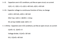
Transcribed Image Text:**Transcription for Educational Website:**
---
### Transient Analysis of Capacitor Circuits
#### Initial Conditions: \( t < 0 \)
- **Capacitors' Behavior:** In DC conditions, capacitors act like an open circuit with no current flow.
- **Voltages and Currents:**
- \( i_1(0^-) = 0 \)
- \( i_2(0^-) = 0 \)
- \( v_1(0^-) = 60 \, \text{Volt} \)
- \( v_2(0^-) = 60 \, \text{Volt} \)
#### At the Moment After Switching: \( t = 0^+ \)
- **Continuity of Capacitor Voltage:** The capacitor voltage remains continuous; hence, there is no change.
- **Voltages:**
- \( v_1(0^+) = 60 \, \text{Volt} \)
- \( v_2(0^+) = 60 \, \text{Volt} \)
- **Current Calculations Using Ohm’s Law:**
- \( i_1(0^+) = \frac{-60}{30} = -2 \, \text{Amp} \)
- **Kirchhoff's Current Law (KCL) at Top Middle Node:**
- \( i_2(0^+) = 0 \)
#### Behavior Over Time: \( t \rightarrow \infty \)
- **Capacitors' Behavior:** In DC conditions, capacitors act like an open circuit with no current flow.
- **Voltages and Currents:**
- \( i_1(\infty) = 0 \)
- \( i_2(\infty) = 0 \)
- **Voltage Divider Principle:**
- \( V_1(\infty) = 30 \, \text{Volt} \)
- **Using Kirchhoff's Voltage Law (KVL):**
- \( V_2(\infty) = 40 \, \text{Volt} \)
---
This analysis outlines the foundational behavior of capacitors in DC circuits, emphasizing initial and steady-state conditions. It is critical for understanding how capacitors impact current and voltage over time in electrical circuits.

Transcribed Image Text:**Question #13:** The switch in the circuit has been open for a long time (resulting in no current flow) and then closes at time \( t = 0 \). Determine the voltages \( v_1 \) and \( v_2 \), and the currents \( i_1 \) and \( i_2 \) at three specific instances: right before the switch closes, immediately after it closes, and a long duration after the switch has closed.
**Circuit Diagram Details:**
- **Components:**
- One 30 Ω resistor in series with a capacitor \( C_1 \).
- A 10 Ω resistor.
- A 50 Ω resistor.
- A 20 Ω resistor.
- A 60 V voltage source.
- Two capacitors are marked with voltages \( v_1 \) and \( v_2 \).
- The currents flowing through the capacitors are labeled as \( i_1 \) and \( i_2 \), respectively.
- **Configuration:**
- The switch is initially open, interrupting the path and preventing current flow through the circuit.
- Upon closing the switch (at \( t = 0 \)), the circuit becomes a closed loop allowing current to flow.
**Analysis:**
- Analyze the circuit in three timeframes:
1. **Just before the switch closes:** Assuming initial conditions with capacitors fully discharged or in a steady state without current flow.
2. **Just after the switch closes:** Consider transient analysis as the circuit begins to conduct current, affecting voltages across capacitors and current through resistors.
3. **A long time after switch closure:** Likely reaching a steady state where capacitors are fully charged according to the DC steady state.
The analysis helps in understanding transient and steady-state behavior in RLC circuits.
Expert Solution
This question has been solved!
Explore an expertly crafted, step-by-step solution for a thorough understanding of key concepts.
This is a popular solution
Trending nowThis is a popular solution!
Step by stepSolved in 3 steps with 4 images

Knowledge Booster
Learn more about
Need a deep-dive on the concept behind this application? Look no further. Learn more about this topic, electrical-engineering and related others by exploring similar questions and additional content below.Similar questions
Recommended textbooks for you
 Introductory Circuit Analysis (13th Edition)Electrical EngineeringISBN:9780133923605Author:Robert L. BoylestadPublisher:PEARSON
 Delmar's Standard Textbook Of ElectricityElectrical EngineeringISBN:9781337900348Author:Stephen L. HermanPublisher:Cengage Learning
 Programmable Logic ControllersElectrical EngineeringISBN:9780073373843Author:Frank D. PetruzellaPublisher:McGraw-Hill Education
 Fundamentals of Electric CircuitsElectrical EngineeringISBN:9780078028229Author:Charles K Alexander, Matthew SadikuPublisher:McGraw-Hill Education
 Electric Circuits. (11th Edition)Electrical EngineeringISBN:9780134746968Author:James W. Nilsson, Susan RiedelPublisher:PEARSON
 Engineering ElectromagneticsElectrical EngineeringISBN:9780078028151Author:Hayt, William H. (william Hart), Jr, BUCK, John A.Publisher:Mcgraw-hill Education,

Introductory Circuit Analysis (13th Edition)
Electrical Engineering
ISBN:9780133923605
Author:Robert L. Boylestad
Publisher:PEARSON

Delmar's Standard Textbook Of Electricity
Electrical Engineering
ISBN:9781337900348
Author:Stephen L. Herman
Publisher:Cengage Learning

Programmable Logic Controllers
Electrical Engineering
ISBN:9780073373843
Author:Frank D. Petruzella
Publisher:McGraw-Hill Education

Fundamentals of Electric Circuits
Electrical Engineering
ISBN:9780078028229
Author:Charles K Alexander, Matthew Sadiku
Publisher:McGraw-Hill Education

Electric Circuits. (11th Edition)
Electrical Engineering
ISBN:9780134746968
Author:James W. Nilsson, Susan Riedel
Publisher:PEARSON

Engineering Electromagnetics
Electrical Engineering
ISBN:9780078028151
Author:Hayt, William H. (william Hart), Jr, BUCK, John A.
Publisher:Mcgraw-hill Education,