
Power System Analysis and Design (MindTap Course List)
6th Edition
ISBN: 9781305632134
Author: J. Duncan Glover, Thomas Overbye, Mulukutla S. Sarma
Publisher: Cengage Learning
expand_more
expand_more
format_list_bulleted
Related questions
Question
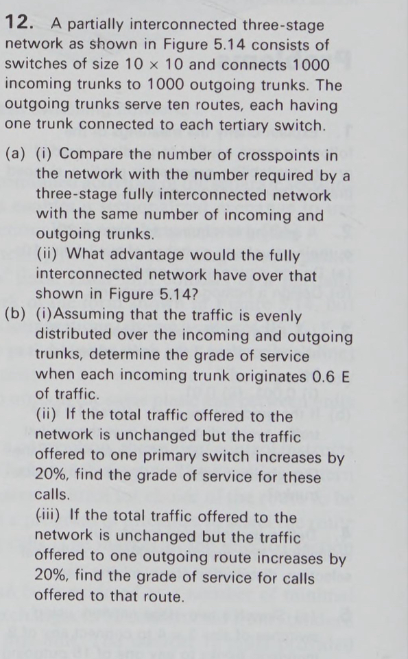

Transcribed Image Text:12. A partially interconnected three-stage
network as shown in Figure 5.14 consists of
switches of size 10 x 10 and connects 1000
incoming trunks to 1000 outgoing trunks. The
outgoing trunks serve ten routes, each having
one trunk connected to each tertiary switch.
(a) (i) Compare the number of crosspoints in
the network with the number required by a
three-stage fully interconnected network
with the same number of incoming and
outgoing trunks.
(ii) What advantage would the fully
interconnected network have over that
shown in Figure 5.14?
(b) (i) Assuming that the traffic is evenly
distributed over the incoming and outgoing
trunks, determine the grade of service
when each incoming trunk originates 0.6 E
of traffic.
(ii) If the total traffic offered to the
network is unchanged but the traffic
offered to one primary switch increases by
20%, find the grade of service for these
calls.
(iii) If the total traffic offered to the
network is unchanged but the traffic
offered to one outgoing route increases by
20%, find the grade of service for calls
offered to that route.

Transcribed Image Text:N = n³ outgoing trunks
n
n primary
switches
NA-links
n secondary
switches
NB-links
ntertiary
switches
Х
nxn
Х
nxn
✗
n
nxn
n
Х
nxn
Х
nxn
n
Х
nx n
Frame n
Х
nxn
✗
nx n
Х
nx n
n
n
Х
✗
nx n
nxn
Frame 1
✗
n
nx n
Figure 5.14 Partially interconnected three-stage network.
n
N = n³ incoming trunks
Expert Solution
This question has been solved!
Explore an expertly crafted, step-by-step solution for a thorough understanding of key concepts.

Step by stepSolved in 2 steps

Knowledge Booster

Similar questions
- Psparrow_forwardsolve thisarrow_forward5.1 Determine the three zone settings for the relay Rab in the system shown in Figure 5.26. The system nominal voltage is 138 kV, and the positive sequence impedances for the various elements are given in the figure. The transformer impedance is given in ohms as viewed from the 138 kV side. Assume that the maximum load at the relay site is 120 MVA, and select a CT ratio accordingly. The available distance relay has zone 1 and zone 2 settings from 0.2 to 10 2, and zone 3 settings from 0.5 to 40 2, in increments of 0.1 2. The angle of maximum torque can be adjusted to 75° or 80°. Remember that the zone 3 of the relay must back up the line BC, as well as the transformer. A Rab (3+j40) B (2+ j50) (0+j9) с Fu D Figure 5.26 System for problem 5.1arrow_forward
- Discuss the implications of using aerial cabling versus underground cabling for network installations.arrow_forwardSome electricians do not bother to calculate the minimum size of neutral service conductor. They size the minimum ungrounded conductor size and then use this information to determine the minimum neutral conductor size. Explain how they determine the minimum neutral size using the minimum ungrounded conductor sizarrow_forwardDerrive the equation for impedance and phase shift for Series RLC circuit Connect to the AC Supply, Also draw an impedance Triangle and voltage triangle.(Sir I need more details for this question.Thanks.)arrow_forward
arrow_back_ios
SEE MORE QUESTIONS
arrow_forward_ios
Recommended textbooks for you
- Power System Analysis and Design (MindTap Course ...Electrical EngineeringISBN:9781305632134Author:J. Duncan Glover, Thomas Overbye, Mulukutla S. SarmaPublisher:Cengage Learning
Power System Analysis and Design (MindTap Course ...
Electrical Engineering
ISBN:9781305632134
Author:J. Duncan Glover, Thomas Overbye, Mulukutla S. Sarma
Publisher:Cengage Learning