
Introductory Circuit Analysis (13th Edition)
13th Edition
ISBN: 9780133923605
Author: Robert L. Boylestad
Publisher: PEARSON
expand_more
expand_more
format_list_bulleted
Related questions
Concept explainers
Question
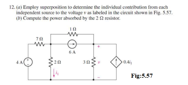

Transcribed Image Text:12. (a) Employ superposition to determine the individual contribution from each
independent source to the voltage v as labeled in the circuit shown in Fig. 5.57.
(b) Compute the power absorbed by the 2 2 resistor.
4 A
ΖΩ
www
www
202
ΤΩ
www
6 A
3 Ω
www
0.4i₁
Fig:5.57
Expert Solution
This question has been solved!
Explore an expertly crafted, step-by-step solution for a thorough understanding of key concepts.

This is a popular solution
Step 1: What is superposition theorem
VIEW Step 2: The voltage v is evaluated when 4V source is applied only
VIEW Step 3: The voltage v is evaluated when 4V source is applied
VIEW Step 4: The voltage v is calculated due to current source
VIEW Step 5: Voltage v is evaluated
VIEW Step 6: Power absorbed by 2 ohm resistance
VIEW Solution
VIEW 
Trending nowThis is a popular solution!

Step by stepSolved in 7 steps with 5 images

Knowledge Booster


Learn more about
Need a deep-dive on the concept behind this application? Look no further. Learn more about this topic, electrical-engineering and related others by exploring similar questions and additional content below.Similar questions
- What are the expected readings of the following in the figure below? (R = 8.90 02, AV = 6.90 V) 10.0 www www 5.00 Ω www R AV R 4.50 V (a) ideal ammeter (Give your answer in mA.) mA (b) ideal voltmeter (Give your answer in volts.) (c) What If? How would the readings in the ammeter (in mA) and voltmeter (in volts) change if the 4.50 V battery was flipped so that its positive terminal was to the right? ideal ammeter ideal voltmeter mA Varrow_forward5.arrow_forwardQ5/ A) Use superposition principle to obtain v, in the circuit below. 30 Ω 10 Ω 20Ω ww ww + v, - 90 V 60 2 4 6 A 30 Ω 40 V wwarrow_forward
- EXERCISE 5.3.26 (a) Find I in the network shown below using source transformation. 6 V(+ 6 ΚΩ ww 6 ΚΩ ww 6 ΚΩ 6 ΚΩ 1₂ 1 mA ? Feedback?arrow_forwardFigure 5 6. For the circuit of Fig. 6, use nodal analysis to determine the currentis. 212 www www 3 A 0 30 70 50 This Figure 6 www 40 60 2 Aarrow_forward
arrow_back_ios
arrow_forward_ios
Recommended textbooks for you
- Introductory Circuit Analysis (13th Edition)Electrical EngineeringISBN:9780133923605Author:Robert L. BoylestadPublisher:PEARSON
 Delmar's Standard Textbook Of ElectricityElectrical EngineeringISBN:9781337900348Author:Stephen L. HermanPublisher:Cengage Learning
 Programmable Logic ControllersElectrical EngineeringISBN:9780073373843Author:Frank D. PetruzellaPublisher:McGraw-Hill Education
  Fundamentals of Electric CircuitsElectrical EngineeringISBN:9780078028229Author:Charles K Alexander, Matthew SadikuPublisher:McGraw-Hill Education
 Electric Circuits. (11th Edition)Electrical EngineeringISBN:9780134746968Author:James W. Nilsson, Susan RiedelPublisher:PEARSON
 Engineering ElectromagneticsElectrical EngineeringISBN:9780078028151Author:Hayt, William H. (william Hart), Jr, BUCK, John A.Publisher:Mcgraw-hill Education,
Introductory Circuit Analysis (13th Edition)
Electrical Engineering
ISBN:9780133923605
Author:Robert L. Boylestad
Publisher:PEARSON
Delmar's Standard Textbook Of Electricity
Electrical Engineering
ISBN:9781337900348
Author:Stephen L. Herman
Publisher:Cengage Learning
Programmable Logic Controllers
Electrical Engineering
ISBN:9780073373843
Author:Frank D. Petruzella
Publisher:McGraw-Hill Education
Fundamentals of Electric Circuits
Electrical Engineering
ISBN:9780078028229
Author:Charles K Alexander, Matthew Sadiku
Publisher:McGraw-Hill Education
Electric Circuits. (11th Edition)
Electrical Engineering
ISBN:9780134746968
Author:James W. Nilsson, Susan Riedel
Publisher:PEARSON
Engineering Electromagnetics
Electrical Engineering
ISBN:9780078028151
Author:Hayt, William H. (william Hart), Jr, BUCK, John A.
Publisher:Mcgraw-hill Education,