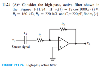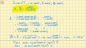
For this question i get all the way to the point where i have a + bj [ 0.0166 + 0.1502j ] however, calculating the phase of this specific question just does not match up with the answer provided by my university.
the formula that i am using is that the phase = 90-arctan(Imaginary/Real) which in this particular problem should add output a phase of -96,31 degrees. However it does only output 6,31 and the input voltage does not contain -90 so i dont get it.

Trending nowThis is a popular solution!
Step by stepSolved in 3 steps with 7 images

This is the solution provided by my school. Why is the phase calculated using -90-arctan? is this just incorrect??

This is the solution provided by my school. Why is the phase calculated using -90-arctan? is this just incorrect??

- Circuitsarrow_forwardConsider a circuit where an ideal inductor L=0.144H is connected in parallel to a resistor R=1.00kΩ. This combination is connected in series with a capacitor C=3.67e-07F. This combination in connected to a power supply source of frequency f=3.4kHz. To study this circuit you need to draw a phasor diagram. Note the sum of the current phasors through the resistor and the inductor must be equal to the phasor representing the current through the capacitor (i.e. the total current). You should draw the phasor for the current through the capacitor on the horizontal axis, since this is also the total current delivered by the supply. The angle between this phasor and that of the power supply represents the phase angle ?.Note that the voltage across the inductor equals the voltage across the resistor since they connected parallel to each other. Furthermore the sum of the phasors representing the currents through the inductor and the resistor equals the phasor representing the current through the…arrow_forwardthank you can you hand write clear pleasearrow_forward
- Please answer in typing formatarrow_forwardThis isn't apart of a test it is a homework question I added an image that contains the figure for this problem An RLC��� circuit with a 15 μF�F capacitor is connected to a variable-frequency power supply with an rms output voltage of 6.8 VV . The rms current in the circuit as a function of the driving frequency appears as in (Figure 1) . Part A What is the value of the resistor? Express your answer to two significant figures and include the appropriate units. figure 1 image for this question. Question 2 John is changing a lightbulb in a lamp. It's a warm summer evening, and the resistance of his damp skin is only 3300 ΩΩ . While one hand is holding the grounded metal frame of the lamp, the other hand accidentally touches the hot electrode in the base of the socket. The voltage of the socket is 120 VV . Use the data shown in (Figure 1) . Part A What is the current through his torso? Express your answer with the appropriate units.arrow_forwardISMA 3K un 3K un + Vs 7mH 3√1₂ Im mn SmH -+ 20 V t IMF Vc What is Vs. iz Ve at steady-state?arrow_forward
- QUESTION 4 A 1kO resistor, a 5mH ideal inductor, and a 1nF capacitor are connected in parallel. Find the total impedance if a 12kHz voltage is applied across the circuit. O 1.26KNL79.9* O 1.890412.4° O 1.61kQ<-74.4° O 3620268.8°arrow_forwardTutorial exercise Jimmy the Circuit Builder is at it again and this time he is using AC. He has all of the linear components in pairs: two AC voltage sources, two AC current sources, two resistors, two capacitors and two inductors. He is trying to build circuits to create certain voltages and currents. All of the sources operate at w=500 rad/s. 940° V 2 <90° A - 12<60° V 1-30° A (c) V=6490° V (d) I=64150° A (e) I = 0.6 +j1.04 (f) V=18.25434.7° V + (a) Draw the circuit. (b) Calculate the voltage across each component. 100μF TE 1mF 46 392 -M 1mH hint: try combining the two sources 10mH Jimmy first builds one circuit to check his understanding of AC voltage, current and power. The circuit is a series connection of the 12 <60° V voltage source, the 3 resistor, the 10 mH inductor, and the 1mF capacitor. 1092 M Using only two elements, connect the pair of elements to create the following AC voltage and currents: Using exactly three elements, draw circuits to create the following AC voltage…arrow_forwardA 15µF capacitor and a 470 ohm resistor are connected in series with a function generator. The supply voltage is 50V RMS 40Hz. Find the reactive power for this circuit.arrow_forward
- What are phasors and what is this equation?arrow_forwardSolve for Vp and Vs. Show your complete solution. (When you try to simulate the circuit in LTSpice where (Vin=0 DC Offset, 10V amplitude, 1MHz frequency), Vp=8V and Vs=40V. I want to learn how to get these values by solving) Will upvote is complete solution and correct. Thank you.arrow_forwardb) Derive a block diagram model for the RLC series circuit shown in Figure Q1, relating input voltage Vin to output voltage Vout derived across the inductor. Your answer should identify the state variables, list the governing equations, and clearly show the direction of flow of signals in the block diagram. R + Vin(~ C Figure Q1 0.000 Voutarrow_forward
 Introductory Circuit Analysis (13th Edition)Electrical EngineeringISBN:9780133923605Author:Robert L. BoylestadPublisher:PEARSON
 Delmar's Standard Textbook Of ElectricityElectrical EngineeringISBN:9781337900348Author:Stephen L. HermanPublisher:Cengage Learning
 Programmable Logic ControllersElectrical EngineeringISBN:9780073373843Author:Frank D. PetruzellaPublisher:McGraw-Hill Education
 Fundamentals of Electric CircuitsElectrical EngineeringISBN:9780078028229Author:Charles K Alexander, Matthew SadikuPublisher:McGraw-Hill Education
 Electric Circuits. (11th Edition)Electrical EngineeringISBN:9780134746968Author:James W. Nilsson, Susan RiedelPublisher:PEARSON
 Engineering ElectromagneticsElectrical EngineeringISBN:9780078028151Author:Hayt, William H. (william Hart), Jr, BUCK, John A.Publisher:Mcgraw-hill Education,


