Introductory Circuit Analysis (13th Edition)
13th Edition
ISBN: 9780133923605
Author: Robert L. Boylestad
Publisher: PEARSON
expand_more
expand_more
format_list_bulleted
Question
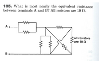
Please answer following question in the picture as details possible.
Please redraw the given circuit (and explain how the resistance that are in cross should be shown)
Please show any shortcut

Transcribed Image Text:105. What is most nearly the equivalent resistance
between terminals A and B? All resistors are 10 N.
A.
all resistors
are 10 N
B
Expert Solution
This question has been solved!
Explore an expertly crafted, step-by-step solution for a thorough understanding of key concepts.
This is a popular solution
Trending nowThis is a popular solution!
Step by stepSolved in 2 steps with 1 images

Knowledge Booster
Similar questions
- 6. In a parallel circuit, the total resistance is _____ value resistor. Select one: A. LARGER THAN THE LOWEST B. LESS THAN THE LOWEST C. EQUAL TO THE LARGEST D. EQUAL TO THE LOWESTarrow_forwardCould you please explain why is a voltage divider used in this circuit? What does vth,rth,gm and the symbol that is equal to B/gm mean? Thank you so mucharrow_forwardParallel Circuits Review In a Parallel circuit, the Voltage across each cell is the same, while the total current is equal to sum of the currents in each resistor. In a series circuits, the total voltage is equal the sum of the voltages across each resistor. The current, however is the same for each resistor, 1. The circuit shown in the diagram consists of two resistors connected in parallel to a cell. The value of Itotal is equal to 30 A. What is the value of V(2)? 50 -ww www 2. The circuit shown in the diagram consists of two resistors connected in parallel to a cell. The value of the current given by the second ammeter, / is 3 A. What is the value of I (total)? 3. A student sets up the circuit shown in the diagram. The value of Itotal is 8 A and the value of I is 6 A. w www a). What is the value of /(2)? b). What is the potential difference supplied by the cell the circuit?arrow_forward
- 1. Type of circuit? 2. What is the total resistance? 3. What is current flow through R1 and R2 ? 4. What is voltage across R1 and R2 ?arrow_forwardMatch each circuit from part 3(A,B,C,D) with the approximate total resistance in that circuit. You may use the same answer more than oncearrow_forwardCan I have help with this worksheet please?arrow_forward
- why are you using the high voltage to find the open circuit angle in step 1? isnt the low voltage supposed to be applied in the open-circuit test?arrow_forward#012 Please help me answer this problem. Choose the correct answer from the given choices. NOTE: Show your solutions or answers why you've got or undergone this answer. Box your final answer. Make sure your answer is in the given choices. Write only your step by step solutions and answers in a clear bondpaper. Make sure the penmanship and photos are clear and readable. Thank you.arrow_forward4-5) Before the advent of ohmmeters (even the analog ones), unknown resistances (Runk) were measured using a Wheatstone bridge. The unknown resistance is placed into the circuit at right as shown. The values of R1 and R2 are extremely well known. The resistance of Rvar is adjusted until the meter Runk. Rvar R1. R2 reads no current in the cross branch. The value of Rvar is then read from a dial. Show that Runk can be found from R1 -Ry Ruknarrow_forward
arrow_back_ios
arrow_forward_ios
Recommended textbooks for you
 Introductory Circuit Analysis (13th Edition)Electrical EngineeringISBN:9780133923605Author:Robert L. BoylestadPublisher:PEARSON
 Delmar's Standard Textbook Of ElectricityElectrical EngineeringISBN:9781337900348Author:Stephen L. HermanPublisher:Cengage Learning
 Programmable Logic ControllersElectrical EngineeringISBN:9780073373843Author:Frank D. PetruzellaPublisher:McGraw-Hill Education
 Fundamentals of Electric CircuitsElectrical EngineeringISBN:9780078028229Author:Charles K Alexander, Matthew SadikuPublisher:McGraw-Hill Education
 Electric Circuits. (11th Edition)Electrical EngineeringISBN:9780134746968Author:James W. Nilsson, Susan RiedelPublisher:PEARSON
 Engineering ElectromagneticsElectrical EngineeringISBN:9780078028151Author:Hayt, William H. (william Hart), Jr, BUCK, John A.Publisher:Mcgraw-hill Education,

Introductory Circuit Analysis (13th Edition)
Electrical Engineering
ISBN:9780133923605
Author:Robert L. Boylestad
Publisher:PEARSON

Delmar's Standard Textbook Of Electricity
Electrical Engineering
ISBN:9781337900348
Author:Stephen L. Herman
Publisher:Cengage Learning

Programmable Logic Controllers
Electrical Engineering
ISBN:9780073373843
Author:Frank D. Petruzella
Publisher:McGraw-Hill Education

Fundamentals of Electric Circuits
Electrical Engineering
ISBN:9780078028229
Author:Charles K Alexander, Matthew Sadiku
Publisher:McGraw-Hill Education

Electric Circuits. (11th Edition)
Electrical Engineering
ISBN:9780134746968
Author:James W. Nilsson, Susan Riedel
Publisher:PEARSON

Engineering Electromagnetics
Electrical Engineering
ISBN:9780078028151
Author:Hayt, William H. (william Hart), Jr, BUCK, John A.
Publisher:Mcgraw-hill Education,