
Introductory Circuit Analysis (13th Edition)
13th Edition
ISBN: 9780133923605
Author: Robert L. Boylestad
Publisher: PEARSON
expand_more
expand_more
format_list_bulleted
Related questions
Concept explainers
Question
At which voltage value will the axis of the output voltage settle?
What is the peak to peak value of the output voltage?
What is the appropriate name for this circuit?
If the diode is positioned in the opposite direction, what type of circuit will the result be?
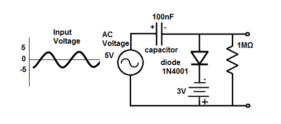

Transcribed Image Text:100nF
Input
Voltage
AC
Voltage
1MQ
5
сарacitor
5V
diode
1N4001
-5
3V
Expert Solution
This question has been solved!
Explore an expertly crafted, step-by-step solution for a thorough understanding of key concepts.

Step by stepSolved in 2 steps with 2 images

Knowledge Booster


Learn more about
Need a deep-dive on the concept behind this application? Look no further. Learn more about this topic, electrical-engineering and related others by exploring similar questions and additional content below.Similar questions
- I need the answer as soon as possiblearrow_forwarddiode? Under what circumstances does the output voltage remain constant in a limiter circuit with Zener When does the Z-current Iz begin to flow? Under what circumstances is the limiting effect maintained even under load?arrow_forwardHow does a diode work in electrical circuits, and what is its construction? Explain the various types of diodes used in electrical engineering and their applications.arrow_forward
- Q-2: The input signal for half-wave rectifier is a.c. signal. The output of 800 load resistor is 50V d.c. voltage. The diode has a resistance of 25 Q. 5 a) Draw the graphs of input signal, diode signal and output signals. 20 b) Calculate the maximum voltage value for the input signal. AC Supply Diode wwwarrow_forwardTopic: Half Wave Rectificationarrow_forwardOne component that does not need to be installed in the correct orientation is a: a. Resistorb. Diodec. Voltage regulatord.arrow_forward
- Draw the output waveform for the given circuit diagram with proper values and also mention the name of the circuit. The input waveform Vi is having a peak-to-peak value of 17 V and the bias voltage is 4 V. Assume diode to be silicon. Vo Maximum value of output waveform Minimum voltage of output waveformarrow_forwardR₁ 54 R₂ D₁ ▷ Figure 1: Precision Rectifier 1. Characterize the relationship of input vs. output for the circuit in Figure 1. That is, find an expression for e. You can use the constant voltage drop model for the diodes. VIarrow_forwardWhat should be the minimum forward voltage applied to a silicon diode to get significant amount of current flowing?arrow_forward
- Example (2-2):- Referring to the series diode configuration of Figure (2-14) (a), and by employing the diode characteristics of Figure (2-14)(b) determine:- VDQ, IDQ and VR ID (mA) 10. IDQ= 9.25mA 8 Q- point ID Load line VR 1KO 6- 4 2 VD(V) VDQ= 0.78 v 10varrow_forwardQ1/Consider the circuit in Figure with a transformer of 10:1 transformation ratio and the diodes are silicon. a) What type of circuit is this? (b) What is the total peak secondary voltage? (c) Find the voltage value across the resistor (d) Sketch the voltage waveform across RL (e) What is the PIV for each diode? D3 D 120 V Pisez) Vpouo D D 10 kn lleeearrow_forwardWhat is the relationship between the input voltage waveform and resistor voltage waveform if the diode is shorted?arrow_forward
arrow_back_ios
SEE MORE QUESTIONS
arrow_forward_ios
Recommended textbooks for you
- Introductory Circuit Analysis (13th Edition)Electrical EngineeringISBN:9780133923605Author:Robert L. BoylestadPublisher:PEARSON
 Delmar's Standard Textbook Of ElectricityElectrical EngineeringISBN:9781337900348Author:Stephen L. HermanPublisher:Cengage Learning
 Programmable Logic ControllersElectrical EngineeringISBN:9780073373843Author:Frank D. PetruzellaPublisher:McGraw-Hill Education
  Fundamentals of Electric CircuitsElectrical EngineeringISBN:9780078028229Author:Charles K Alexander, Matthew SadikuPublisher:McGraw-Hill Education
 Electric Circuits. (11th Edition)Electrical EngineeringISBN:9780134746968Author:James W. Nilsson, Susan RiedelPublisher:PEARSON
 Engineering ElectromagneticsElectrical EngineeringISBN:9780078028151Author:Hayt, William H. (william Hart), Jr, BUCK, John A.Publisher:Mcgraw-hill Education,
Introductory Circuit Analysis (13th Edition)
Electrical Engineering
ISBN:9780133923605
Author:Robert L. Boylestad
Publisher:PEARSON
Delmar's Standard Textbook Of Electricity
Electrical Engineering
ISBN:9781337900348
Author:Stephen L. Herman
Publisher:Cengage Learning
Programmable Logic Controllers
Electrical Engineering
ISBN:9780073373843
Author:Frank D. Petruzella
Publisher:McGraw-Hill Education
Fundamentals of Electric Circuits
Electrical Engineering
ISBN:9780078028229
Author:Charles K Alexander, Matthew Sadiku
Publisher:McGraw-Hill Education
Electric Circuits. (11th Edition)
Electrical Engineering
ISBN:9780134746968
Author:James W. Nilsson, Susan Riedel
Publisher:PEARSON
Engineering Electromagnetics
Electrical Engineering
ISBN:9780078028151
Author:Hayt, William H. (william Hart), Jr, BUCK, John A.
Publisher:Mcgraw-hill Education,