Introductory Circuit Analysis (13th Edition)
13th Edition
ISBN: 9780133923605
Author: Robert L. Boylestad
Publisher: PEARSON
expand_more
expand_more
format_list_bulleted
Question

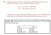
Transcribed Image Text:10.2 Using the values of R and D in each area, for Example 10B, resolve for the
100-MW load change in area 1 under the following conditions:
Area 1: base MVA = 2000 MVA
Area 2: base MVA = 500 MVA
Then solve for a load change of 100 MW occurring in area 2 with R values
and D values as in Example 10B and base MVA for each area as before.
Example 10B: You are given two system areas connected by a tie line with the
following characteristics:
Area 1
Area 2
R=0.01 pu
D=0.8 pu
R=0.02 pu
D=1.0 pu
Base MVA = 500
Base MVA = 500
Expert Solution
This question has been solved!
Explore an expertly crafted, step-by-step solution for a thorough understanding of key concepts.
This is a popular solution
Trending nowThis is a popular solution!
Step by stepSolved in 3 steps with 3 images

Knowledge Booster
Learn more about
Need a deep-dive on the concept behind this application? Look no further. Learn more about this topic, electrical-engineering and related others by exploring similar questions and additional content below.Similar questions
- 10.a. Most of the power transformers that you will find in commercial and industrial applications are either three-phase orA. two-phaseB. single-phaseC. zero-phaseD. four-phase10.b. The percent regulation for a transformer whose secondary voltage goes from 150 V at no load to 140 V at full load isA. 10.7%B. 9.3%C. 6.7%D. 7.1%10.c. Three single-phase transformers are connected in ∆ - ∆. Each of these transformers has a secondary phase current of 10 A. The value of the secondary line current isA. 578 AB. 17.3 AC. 57.8 AD. 1.73 Aarrow_forwarddo the discussion about Power measurement using Wattmeter, Ammeter and Voltmeter & Power measurement using Electronic Single phase measurement. Discuss the differences between both data. Why these problems occur and how to minimize it. Explain the role of power factor.arrow_forwardA surge of 100 kV travels along an overhead line towards its junction with a cable. The surge impedance for the overhead line and cable are 400 ohms and 50 ohms respectively. The magnitude of the surge transmitted through the cable is ?arrow_forward
- Q5/ A three bus power system is shown in Figure (3) The system parameters are given in Tables below. The voltage at bus 2 is maintained at 1.03p.u. The maximum and minimum reactive power limits of the generation at bus 2 are 35 and 0 Mvar respectively. Taking bus 1 as slack bus, obtain the load flow solution using NR iterative method. Zitration Speloomu Vz= 1.3 P=50 MW S2=? Q2020 a S. 435 P.3. Bus Impedance (p.u) 1-2 j0.24 1V31=2 S3 =? 1-3 j0.06 Q3:35 2-3 J0.018 Bus voltage generation load MW Mvar MW Mvar 1 1.05+j 0.0 0 0 ad 2 1.03+j 0.0 30 P 50 20 3 0 ********** Q350 60D 25arrow_forwardDescription In the particular case of figure below derive both the critical clearing angle and the critical clearing time. P, = Pmaz sin d Pm A1 do der Smar A generator having H = 6.R MJ/MVA is delivering power of 1.0 per unit to an infinite bus through a purely reactive network when the occurrence of a fault reduces the generator output power to zero. The maximum power that could be delivered is 2.5S per unit. When the fault is cleared, the original network conditions again exist. Determine the critical clearing angle and critical clearing time. (Roll=PQRS)arrow_forwardQ2) The bus-bar (A) and (B) are linked by a bus-bar reactor of 1000 KVA with 10% reactance on bus-bar (A). The system has 2 generators each one of 5000 KVA with 5 % reactance, and on bus-bar (B) two motors each one of 5000 KVA with 12% reactance. Find the steady state apparent power (MVA) given to the symmetrical short circuit occurred on bus-bar (B) in the circuit shown below. Ма Mi B Gi A G₂ Xr marrow_forward
arrow_back_ios
arrow_forward_ios
Recommended textbooks for you
 Introductory Circuit Analysis (13th Edition)Electrical EngineeringISBN:9780133923605Author:Robert L. BoylestadPublisher:PEARSON
 Delmar's Standard Textbook Of ElectricityElectrical EngineeringISBN:9781337900348Author:Stephen L. HermanPublisher:Cengage Learning
 Programmable Logic ControllersElectrical EngineeringISBN:9780073373843Author:Frank D. PetruzellaPublisher:McGraw-Hill Education
 Fundamentals of Electric CircuitsElectrical EngineeringISBN:9780078028229Author:Charles K Alexander, Matthew SadikuPublisher:McGraw-Hill Education
 Electric Circuits. (11th Edition)Electrical EngineeringISBN:9780134746968Author:James W. Nilsson, Susan RiedelPublisher:PEARSON
 Engineering ElectromagneticsElectrical EngineeringISBN:9780078028151Author:Hayt, William H. (william Hart), Jr, BUCK, John A.Publisher:Mcgraw-hill Education,

Introductory Circuit Analysis (13th Edition)
Electrical Engineering
ISBN:9780133923605
Author:Robert L. Boylestad
Publisher:PEARSON

Delmar's Standard Textbook Of Electricity
Electrical Engineering
ISBN:9781337900348
Author:Stephen L. Herman
Publisher:Cengage Learning

Programmable Logic Controllers
Electrical Engineering
ISBN:9780073373843
Author:Frank D. Petruzella
Publisher:McGraw-Hill Education

Fundamentals of Electric Circuits
Electrical Engineering
ISBN:9780078028229
Author:Charles K Alexander, Matthew Sadiku
Publisher:McGraw-Hill Education

Electric Circuits. (11th Edition)
Electrical Engineering
ISBN:9780134746968
Author:James W. Nilsson, Susan Riedel
Publisher:PEARSON

Engineering Electromagnetics
Electrical Engineering
ISBN:9780078028151
Author:Hayt, William H. (william Hart), Jr, BUCK, John A.
Publisher:Mcgraw-hill Education,