Structural Analysis
6th Edition
ISBN: 9781337630931
Author: KASSIMALI, Aslam.
Publisher: Cengage,
expand_more
expand_more
format_list_bulleted
Question
I need detailed help solving this exercise from homework of Applied Mechanics.
I do not really understand how to do, please do it step by step, not that long but clear. Thank you!

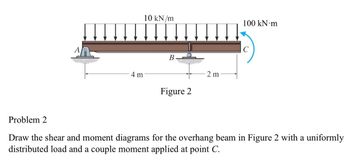
Transcribed Image Text:10 kN/m
100 kN·m
A
B
2 m
4 m
Figure 2
C
Problem 2
Draw the shear and moment diagrams for the overhang beam in Figure 2 with a uniformly
distributed load and a couple moment applied at point C.
Expert Solution
This question has been solved!
Explore an expertly crafted, step-by-step solution for a thorough understanding of key concepts.
Step by stepSolved in 2 steps with 4 images

Knowledge Booster
Similar questions
- Part 2 (Statically Indeterminate Beams) Problem 1. Draw the shear and Bending Moment Diagram of the beam shown. Use the Method of Superposition P1 P2 A P1 66.00KN a P2 48.00KN B L a 2.80m с b 1.80m b L 7.10m Darrow_forward65KN 3m 3m B 18KN/m 5m 30KN/m 50° A Analyze the strudure draw Shear, Axial and Moment Diagramarrow_forwardB8arrow_forward
- Draw the shear and moment diagram of the following beams. Let P = 9arrow_forwardDraw the Shear and moment diagram using method of section and method of areaarrow_forwardProblem 4 The beam AB is subjected to the uniformly distributed load shown and to two unknown forces P and Q. Knowing that the bending moment is +800 Nm at D and +1300 Nm at E, (a) determine P and Q, (b) draw the shear and bending-moment diagrams for the beam. A 20 kN/m C P Q 1. 1. D E 0.3 m 0.3 m 0.3 m 0.3 m B un M' (a) Internal forces (positive shear and positive bending moment)arrow_forward
- Draw the shear and moment diagram of the following beams. Let P = 13 2PKN PkN/m A E B D 1.0 m 1.0 m 2 marrow_forward3. Draw the shear and moment diagram of the structure shown below. 50 kN d A C D 2 m2 m2 m 20 kN/m Barrow_forwardThe beam is subjected to the uniform distributed load shown. Draw the shear and moment diagrams for the beam. 2 kN /m |A B 15 m TC -2 m-arrow_forward
- Bending moment is known in the beam ABC in section B: MB = -10 kNmThe magnitude of the charge w.Draw the shear force and bending moment diagrams for section ABCDE.arrow_forwardAnalyze the frame shown and draw the shear, moment and axial diagram. b d 3m 25kN - 4 m e1.5 m a. 2 at 4 m = 8 marrow_forwardDraw the shear and bending moment curves for the beam and loadingshown, (b) the maximum absolute value of the shear andbending moment in the beam by the semi-graphical method. F2= 36 kN w2= 21 kN/marrow_forward
arrow_back_ios
SEE MORE QUESTIONS
arrow_forward_ios
Recommended textbooks for you

 Structural Analysis (10th Edition)Civil EngineeringISBN:9780134610672Author:Russell C. HibbelerPublisher:PEARSON
 Principles of Foundation Engineering (MindTap Cou...Civil EngineeringISBN:9781337705028Author:Braja M. Das, Nagaratnam SivakuganPublisher:Cengage Learning
 Fundamentals of Structural AnalysisCivil EngineeringISBN:9780073398006Author:Kenneth M. Leet Emeritus, Chia-Ming Uang, Joel LanningPublisher:McGraw-Hill Education
 Traffic and Highway EngineeringCivil EngineeringISBN:9781305156241Author:Garber, Nicholas J.Publisher:Cengage Learning


Structural Analysis (10th Edition)
Civil Engineering
ISBN:9780134610672
Author:Russell C. Hibbeler
Publisher:PEARSON

Principles of Foundation Engineering (MindTap Cou...
Civil Engineering
ISBN:9781337705028
Author:Braja M. Das, Nagaratnam Sivakugan
Publisher:Cengage Learning

Fundamentals of Structural Analysis
Civil Engineering
ISBN:9780073398006
Author:Kenneth M. Leet Emeritus, Chia-Ming Uang, Joel Lanning
Publisher:McGraw-Hill Education


Traffic and Highway Engineering
Civil Engineering
ISBN:9781305156241
Author:Garber, Nicholas J.
Publisher:Cengage Learning