
Related questions
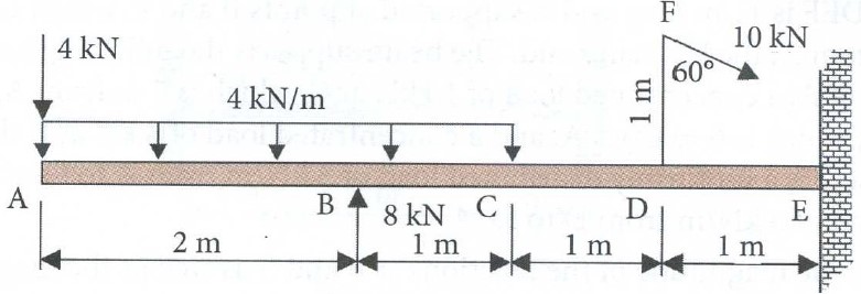
Figure 3 represents a cantilever beam A, B, C, D, E clamped at point E and carrying various types of loads. A load of 10 kN as shown, is applied on the beam through a vertical lever DF of 1 m length rigidly attached to the beam.
1. Determine and show the directions of all support reactions at point E.
2. Using the left free-end A as the origin of the horizontal coordinate of the sections, establish the equations for shear force (SF) and bending moment (BM) acting in each cross-section of the beam. Equations must be worked out and finalized to their standard forms.
3. Plot the SF and BM diagrams for each cross-section of the beam. Each part of the diagrams must be supported by established SF and BM equations. A deviation from the correct relative layout of the configuration of the beam, SF and BM diagrams will be penalized.


Step by stepSolved in 2 steps with 5 images


 Structural Analysis (10th Edition)Civil EngineeringISBN:9780134610672Author:Russell C. HibbelerPublisher:PEARSON
 Principles of Foundation Engineering (MindTap Cou...Civil EngineeringISBN:9781337705028Author:Braja M. Das, Nagaratnam SivakuganPublisher:Cengage Learning
 Fundamentals of Structural AnalysisCivil EngineeringISBN:9780073398006Author:Kenneth M. Leet Emeritus, Chia-Ming Uang, Joel LanningPublisher:McGraw-Hill Education
 Traffic and Highway EngineeringCivil EngineeringISBN:9781305156241Author:Garber, Nicholas J.Publisher:Cengage Learning