Elements Of Electromagnetics
7th Edition
ISBN: 9780190698614
Author: Sadiku, Matthew N. O.
Publisher: Oxford University Press
expand_more
expand_more
format_list_bulleted
Question

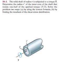
Transcribed Image Text:10-1. The solid shaft of radius r is subjected to a torque T.
Determine the radius r' of the inner core of the shaft that
resists one-half of the applied torque (T/2). Solve the
problem two ways: (a) by using the torsion formula, (b) by
finding the resultant of the shear-stress distribution.
Expert Solution
This question has been solved!
Explore an expertly crafted, step-by-step solution for a thorough understanding of key concepts.
This is a popular solution
Trending nowThis is a popular solution!
Step by stepSolved in 4 steps

Knowledge Booster
Similar questions
- 5-3. The solid shaft is fixed to the support at C and subjected to the torsional loadings shown. Determine the shear stress at points A and B and sketch the shear stress on volume elements located at these points. 10 kN-m 75 mm BE 4 kN-m -75 mm 50 mmarrow_forwarddraw fbd and show solutionarrow_forwardA circular solid shaft has a diameter of 60 mm and is subjected to a torque load of 8.7 kN•m. Determine the resulting torque maximum and minimum shear stress.arrow_forward
- The two shafts are made of A-36 steel (shear modulus G = 75 MPa). Each has a diameter of 25 mm, and they are supported by bearings at A, B, and C, which allow free rotation. If the support at D is fixed, determine a.) the angle of twist of end A and b.) the maximum torsional stress in the shaft, when the two torques of 60 N-m are applied to the assembly as shown, one on shaft ABand the other on shaft CD .arrow_forward1-63.M. The key in Figure 1-18 has the dimensions b = 10 min, h = 8 nim, and L = 22 min. Determine the shear stress in the key when 95 N-m of torque is transferred from the 35-mm-diameter shaft to the hub. Hub End view Shear plane Shear pl T=Torque -D=Shaft diameter T=F(D/2) F₁-Force of shaf F₂= Force of hub on 1 Shear area=A,=bxLarrow_forwardonly HANDWRITTEN answer needed ( NOT TYPED)arrow_forward
- *RIO4. The shaft has a radius cand is subjected to a torque per unit length of t, which is distributed uniformly over the shaft's entire length L. If it is fixed at its far end A, determine the angle of twist d of end B. The shear modulus is G.arrow_forwardThe composite shaft consists of a mid-section that includes the 1-in. diameter solid shaft and a tube that is welded to the rigid flanges at A and B. Neglect the thickness of the flanges. The shaft is subjected to a torque of T=950 lb-ft. The material is A-38 steel, G = 11 x 10³ ksi- (Eigure 1) T 1 in. 3 in. 0.25 in. 0.75 ft. B 0.5 ft Determine the angle of twist of end C of the shaft relative to end D.arrow_forward5-3. The solid shaft is fixed to the support at C and subjected to the torsional loadings shown. Determine the shcar stress at points A and B and sketch the shear stress on volume clements located at these points 10 kN-m 75 mm 4 kN-m 75 mm 50 mmarrow_forward
- The shaft has an outer diameter of 1.5 in. and an inner diameter of 0.8 in. If it is subjected to the applied torques as shown, determine the shear stress distribution on the cross-section within region EA. The smooth bearings at A and B do not resist torque 1500 lb-in. E 2100 lb-in. B 600 lb.in.arrow_forwardMechanics of materials Iarrow_forwardThe two shafts are made of steel (G=11x106 lb/in2). Each has a diameter of 1 in. , and they are supported by bearings at A, B and C, which allow free rotation. If the support at D is fixed, determine the angle of twist of end A when the torques are applied to the assembly as shown. Torque applied at H of 80 ft lbs, and at G of 40 ft lbs in opposing directions as seen in the figurearrow_forward
arrow_back_ios
SEE MORE QUESTIONS
arrow_forward_ios
Recommended textbooks for you
 Elements Of ElectromagneticsMechanical EngineeringISBN:9780190698614Author:Sadiku, Matthew N. O.Publisher:Oxford University Press
 Mechanics of Materials (10th Edition)Mechanical EngineeringISBN:9780134319650Author:Russell C. HibbelerPublisher:PEARSON
 Thermodynamics: An Engineering ApproachMechanical EngineeringISBN:9781259822674Author:Yunus A. Cengel Dr., Michael A. BolesPublisher:McGraw-Hill Education
 Control Systems EngineeringMechanical EngineeringISBN:9781118170519Author:Norman S. NisePublisher:WILEY
 Mechanics of Materials (MindTap Course List)Mechanical EngineeringISBN:9781337093347Author:Barry J. Goodno, James M. GerePublisher:Cengage Learning
 Engineering Mechanics: StaticsMechanical EngineeringISBN:9781118807330Author:James L. Meriam, L. G. Kraige, J. N. BoltonPublisher:WILEY

Elements Of Electromagnetics
Mechanical Engineering
ISBN:9780190698614
Author:Sadiku, Matthew N. O.
Publisher:Oxford University Press

Mechanics of Materials (10th Edition)
Mechanical Engineering
ISBN:9780134319650
Author:Russell C. Hibbeler
Publisher:PEARSON

Thermodynamics: An Engineering Approach
Mechanical Engineering
ISBN:9781259822674
Author:Yunus A. Cengel Dr., Michael A. Boles
Publisher:McGraw-Hill Education

Control Systems Engineering
Mechanical Engineering
ISBN:9781118170519
Author:Norman S. Nise
Publisher:WILEY

Mechanics of Materials (MindTap Course List)
Mechanical Engineering
ISBN:9781337093347
Author:Barry J. Goodno, James M. Gere
Publisher:Cengage Learning

Engineering Mechanics: Statics
Mechanical Engineering
ISBN:9781118807330
Author:James L. Meriam, L. G. Kraige, J. N. Bolton
Publisher:WILEY