
Elements Of Electromagnetics
7th Edition
ISBN: 9780190698614
Author: Sadiku, Matthew N. O.
Publisher: Oxford University Press
expand_more
expand_more
format_list_bulleted
Related questions
Concept explainers
Question
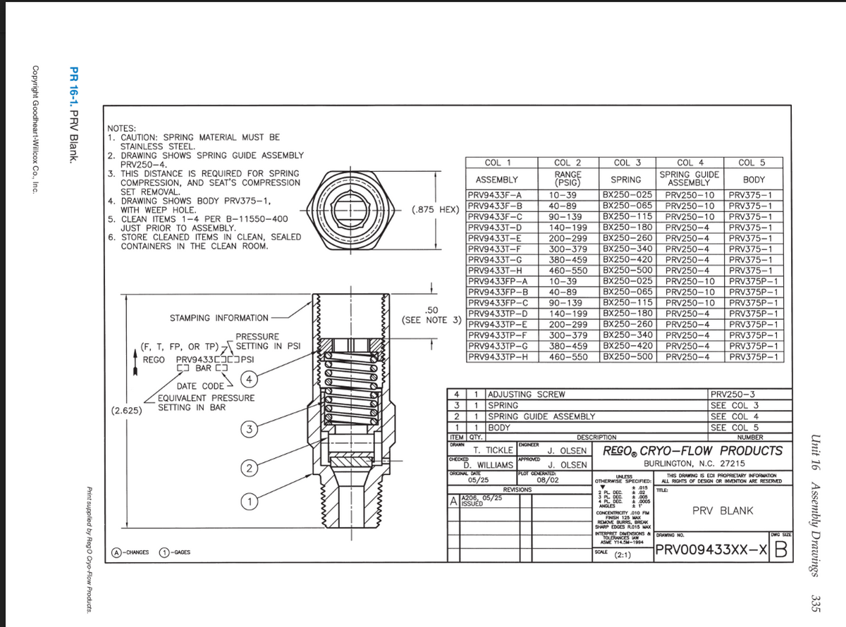
1.How many assemblies are described by this one assembly drawing?
2. Each assembly described by this drawing uses this one part. What is its part number?
3.Which BODY is used for ASSEMBLY PRV9433T-E?
4. How many BODY options are there on this drawing?
5. How will the date code be applied to the assembly?
6. What paper size is the original version of the print?
7. Who checked the drawing? Exactly how it is on the print.
8. What is the scale of the original drawing?
9.Are there any reference measurements on the drawing?
10. Are there any cutting planes on this drawing?
Thank you, please help.

Transcribed Image Text:NOTES:
1. CAUTION: SPRING MATERIAL MUST BE
STAINLESS STEEL.
2. DRAWING SHOWS SPRING GUIDE ASSEMBLY
PRV250-4.
3. THIS DISTANCE IS REQUIRED FOR SPRING
COMPRESSION, AND SEAT'S COMPRESSION
COL 1
COL 2
COL 3
COL 4
COL 5
RANGE
(PSIG)
SPRING GUIDE
ASSEMBLY
ASSEMBLY
SPRING
BODY
SET REMOVAL.
4. DRAWING SHOWS BODY PRV375-1,
WITH WEEP HOLE.
5. CLEAN ITEMS 1-4 PER B-11550-400
JUST PRIOR TO ASSEMBLY.
6. STORE CLEANED ITEMS IN CLEAN, SEALED
PRV9433F-A
10-39
BX250-025
PRV250-10
PRV375-1
40-89
BX250-065
BX250-115
PRV250-10
PRV250-10
PRV375-1
(.875 HEX) PRV9433F-B
PRV9433F-C
PRV9433T-D
PRV9433T-E
PRV9433T-F
PRV9433T-G
PRV9433T-H
PRV9433FP-A
PRV9433FP-B
PRV9433FP-C
PRV9433TP-D
PRV9433TP-E
PRV9433TP-F
PRV9433TP-G
PRV9433TP-H
90-139
140-199
200-299
300-379
PRV375-1
BX250-180
BX250-260
BX250-340
PRV250-4
PRV375-1
PRV375-
PRV375-1
PRV375-1
PRV375-1
PRV250-4
PRV250-4
CONTAINERS IN THE CLEAN ROOM.
380-459
460-550
10-39
BX250-420
PRV250-4
PRV250-4
BX250-500
BX250-025
BX250-065
BX250-115
BX250-180
BX250-260
BX250-340
BX250-420
BX250-500 PRV250-4
PRV250-10
PRV375P-1
PRV375P-1
40-89
90-139
PRV250-10
PRV250-10
PRV375P-1
PRV375P-1
PRV375P-1
PRV375P-1
PRV375P-1
PRV375P-1
.50
140-199
PRV250-4
STAMPING INFORMATION
(SEE NOTE 3)
200-299
PRV250-4
PRV250-4
PRV250-4
PRESSURE
300-379
(F, T, FP, OR TP) SETTING IN PSI
REGO PRV9433CJPSI
25 BAR CJ
(4
380-459
460-550
DATE CODE
EQUIVALENT PRESSURE
SETTING IN BAR
4 1 ADJUSTING SCREW
3 1 SPRING
2 1 SPRING GUIDE ASSEMBLY
1 1 BODY
ITEM QTY.
PRV250-3
SEE COL 3
SEE COL 4
(2.625)
SEE COL 5
NUMBER
DESCRIPTION
DRANN
ENGINEER
T. TICKLE
J. OLSEN
CHECKED
GR
D. WILLIAMS
REGO, CRYO-FLOW PRODUCTS
BURLINGTON, N.C. 27215
APPROVED
J. OLSEN
ORIGINAL DATE
05/25
PLOT GENERATEDT
08/02
THIS DRAWING IS ECI PROPRIETARY INFORMATION
ALL RIGHTS OF DESIGN OR INVENION ARE RESERVED
UNLESS
OTHERWISE SPECIFIED:
* 015
* 02
*005
+ 0005
REVISIONS
TTLE
A206, 05/25
AlsSUED
2 PL DEC.
3 PL DEC.
i PL DEC.
ANGLES
PRV BLANK
CONCENTRICITY 010 FIM
FINISH 125 MAX
REMOVE BURRS, BREAK
SHARP EDGES R015 MAX
INTERPRET DIMENSIONS & DRAWING NO.
TOLERANCES AW
ASME YI4.SM-1994
DWG SIZE
SOLE (2:1)
PRVO09433XX-XB
A-CHANGES
0-GAGES
Unit 16 Assembly Drawings 335
Print supplied by Rego Cryo-Flow Produe
PR 16-1. PRV Blank.
Copyright Goodheart-Willcox Co., Inc
Expert Solution
This question has been solved!
Explore an expertly crafted, step-by-step solution for a thorough understanding of key concepts.

This is a popular solution

Trending nowThis is a popular solution!

Step by stepSolved in 2 steps

Knowledge Booster


Learn more about
Need a deep-dive on the concept behind this application? Look no further. Learn more about this topic, mechanical-engineering and related others by exploring similar questions and additional content below.Similar questions
- Required information Sally is making a sine bar, which is used to machine angles on parts (see the given figure). She has a 1.250-inch-thick bar that needs 90° grooves machined into it for precision ground 1.0000-inch diameter cylinders. A sine bar is used by placing different thicknesses under one of the cylinders so that the proper angle is attained. Sally wants the distance between the centers of the cylinders to be D= 5.4 inches. -D -1.0000 Ø How deep should she mill the 90° grooves so that the top of the sine block is 2 inches tall? The depth of the mill should be inches.arrow_forwardI need answers to questions 1, 2, and 3 pertaining to the print provided. Note: A tutor keeps putting 1 question into 3 parts and wasted so many of my questions. Never had a issue before until now, please allow a different tutor to answer because I was told I am allowed 3 of these questions.arrow_forwardA company is reviewing its policy of putting each sub-assemblybought in from outside through a detailed inspection process ondelivery. The firm can either inspect or not inspect. The sub-assemblymay either come up to the required quality standard (90 % of thetime), or fail to do so (10 % of the time).It costs K10 to inspect a sub-assembly and another K10 to put rightany defect found at that stage. If the sub-assembly is not inspected Page 4 of and is then found to be faulty at the finished goods stage the cost ofrework is K40.Advise the firm what to do.arrow_forward
- An engineer draws an assembled gear in perspective. © 2019 StrongMind How does this gear appear when viewed from above? Ⓒ2020 StrongMind Ⓒ2020 StrongMindarrow_forwardwhat are some Observation and Description of Experimental Setup of key failure using bending testarrow_forwardNeed questions 13, 14, 15 explained and answered please.arrow_forward
- Alert for not submit AI generated answer. I need unique and correct answer. Don't try to copy from anywhere. Do not give answer in image formet and hand writingarrow_forwardO b. 2:1 Oc. 1:2 O d. T: 1 QUESTION 10 What is the maximum tensile load P that can be applied to the bolted joint if the bolt diameter is 20 mm and the shear strength of the bolt material is 120 MNm 2 ? Apply a 'safety factor' of 1.2 in your calculations. Note: Please read about 'safety factors' and how they are applied in calculations. O a. 26.4 Nm2 O b. 26.4 kN O c. 62.5 kN O d. 62.5 MNm2 QUESTION 11arrow_forwardWhat are the TPI and TPF of a part with end diameters of 3/4" and 1/2" and a taper length of 4.25"?arrow_forward
arrow_back_ios
SEE MORE QUESTIONS
arrow_forward_ios
Recommended textbooks for you
- Elements Of ElectromagneticsMechanical EngineeringISBN:9780190698614Author:Sadiku, Matthew N. O.Publisher:Oxford University Press
 Mechanics of Materials (10th Edition)Mechanical EngineeringISBN:9780134319650Author:Russell C. HibbelerPublisher:PEARSON
 Thermodynamics: An Engineering ApproachMechanical EngineeringISBN:9781259822674Author:Yunus A. Cengel Dr., Michael A. BolesPublisher:McGraw-Hill Education
  Control Systems EngineeringMechanical EngineeringISBN:9781118170519Author:Norman S. NisePublisher:WILEY
 Mechanics of Materials (MindTap Course List)Mechanical EngineeringISBN:9781337093347Author:Barry J. Goodno, James M. GerePublisher:Cengage Learning
 Engineering Mechanics: StaticsMechanical EngineeringISBN:9781118807330Author:James L. Meriam, L. G. Kraige, J. N. BoltonPublisher:WILEY
Elements Of Electromagnetics
Mechanical Engineering
ISBN:9780190698614
Author:Sadiku, Matthew N. O.
Publisher:Oxford University Press
Mechanics of Materials (10th Edition)
Mechanical Engineering
ISBN:9780134319650
Author:Russell C. Hibbeler
Publisher:PEARSON
Thermodynamics: An Engineering Approach
Mechanical Engineering
ISBN:9781259822674
Author:Yunus A. Cengel Dr., Michael A. Boles
Publisher:McGraw-Hill Education
Control Systems Engineering
Mechanical Engineering
ISBN:9781118170519
Author:Norman S. Nise
Publisher:WILEY
Mechanics of Materials (MindTap Course List)
Mechanical Engineering
ISBN:9781337093347
Author:Barry J. Goodno, James M. Gere
Publisher:Cengage Learning
Engineering Mechanics: Statics
Mechanical Engineering
ISBN:9781118807330
Author:James L. Meriam, L. G. Kraige, J. N. Bolton
Publisher:WILEY