
Concept explainers
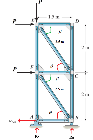
Refer to the truss structure shown above for the following questions. Let P = 5kN.
A. What are the support reactions?
B. Which members are zero force members?
C. Determine the force in members BC, CF, and EF and indicate if the members are in tension or compression.
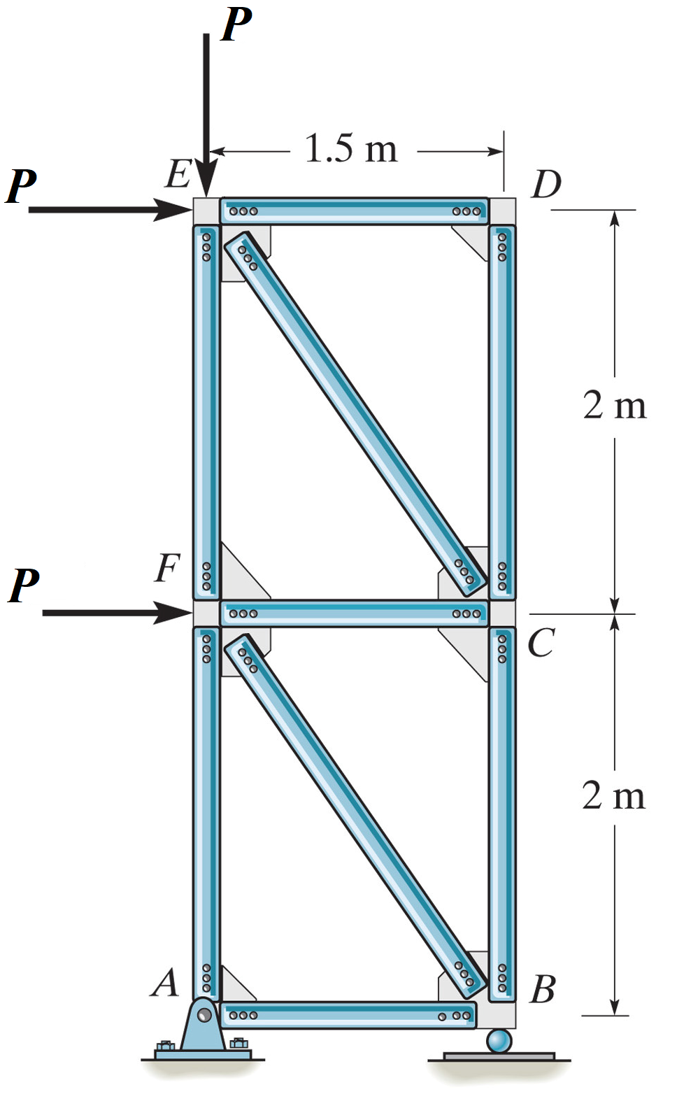
Calculate external determinacy of the truss:

external determinacy of the truss is zero hence support reaction can be calculating by equilibrium equations.
Calculate support reaction at support A and B:
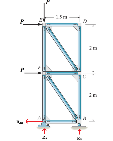
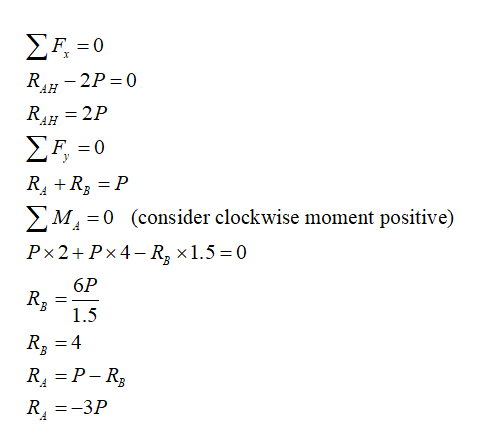
The negative sign indicates that the direction of the reaction at support A is opposite to the sign that we assumed.
Calculate member force:
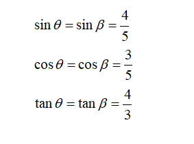
Consider joint A:
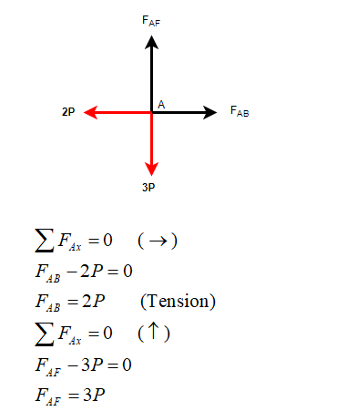
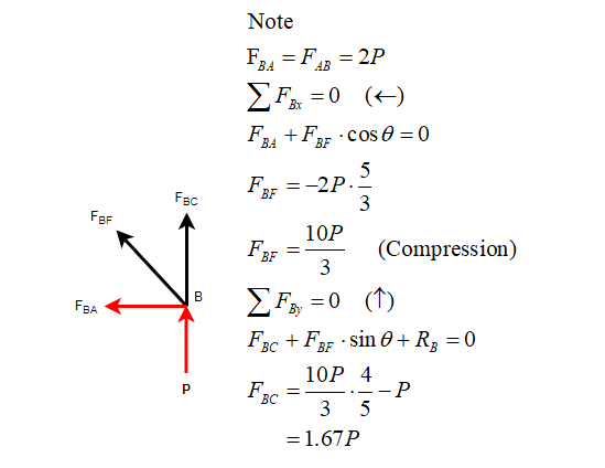
Similarly calculate the member forces in all the member:
Consider joint B:
Trending nowThis is a popular solution!
Step by stepSolved in 10 steps with 11 images

- Q3 The truss ABC shown in the figure supports a horizontal load P-900 lb and a vertical load P2= 300 lb. Both bars have cross-sectional area A-2.4 in. and are made of steel with E-20 X 10 psi. (a) Determine the strain energy U, of the truss when the load P, acts alone (P2 -0). (b) Determine the strain energy U2 when the load P2 acts alone (P 0). (c) Determine the strain energy Uz when both loads act simultaneously. 30 B P =900 lb P2 300 lb 40 in.arrow_forwardFundamental Problem 6.11 Determine the force in members GF, GD, and CD of the truss. State if the members are in tension or compression. Take that P₁ = 12 kN, P₂ = 25 kN and P318 kN (Figure 1) Figure 1 1 m 2 m of 1 H -2 m- B P₁ -2 m- C P₂ -2 m- P3 -2 m-arrow_forwardA pin-connected structure is supported as shown in the figure. Bar (1) is made of brass [E = 105 GPa], and bar (2) is made of an aluminum alloy [E = 70 GPa]. Bars (1) and (2) each have cross-sectional areas of 375 mm². Rigid bar ABCD is supported by a pin in a double-shear connection at B. If the allowable shear stress for pin B is 130 MPa, calculate the minimum allowable diameter for the pin at B when P = 107 kN. P A 880 mm D B 720 mm 430 mm (2) (1) 260 mm 400 mmarrow_forward
- Classify the following truss as statically determinate (SD), statically indeterminate (SI), stable, or unstable. If statically indeterminate, determine the degree of indeterminacy. If unstable, explain why. B m +R- 2J = SD SI O NA Only when SI is selected, then answer SI = Stable Unstable, because a member is missing between A and B Unstable, because there is an internal collapse mechanismarrow_forwardThe static indeterminacy of the structure shown below is G F Hinge. С E B (A)Unstable (B) Stable, determinate (C) Stable, 5th degree indeterminate (D)Stable, 3rd degree indeterminatearrow_forwardAll bars in the truss have the same cross section and material properties. Find the total change in length of the cord A-B-C, and the stress at point p in the coordinate system given. ⁹00 lb AABC = σ= in ksi A = 0.64 in² E 30000 ksi V = 0.29 point p A Y 800 lb. 5 ft B 11200 lb 5 ft C 800 lb F 4 ft 4 ftarrow_forward
- I need the answer as soon as possiblearrow_forwardFor the steel truss (E = 29 x 106 psi) and loading shown, determine the deformations members AB, BC, BE, DE and DF , knowing that their cross-sectional areas are 2 in2.arrow_forward14. A pin-connected structure consists of a rigid beam ABCD and two supporting bars. Bar (1) is an aluminum alloy [E = 70 GPa] with a cross-sectional area of A₁ = 2,400 mm². Bar (2) is a bronze alloy [E = 100 GPa] with a cross-sectional area of A2 = 6,000 mm². All bars are unstressed before the load P is applied. If a load of P = 535 kN is applied at B, determine the normal force in bar (1). A) B) D) E) 2.9 m 0.8 m 391 kN 325 kN 301 kN 247 kN 181 kN B 1.5 m P = 535 KN (2) C 3.3 m 1.2 m F₁ K 0.8m D + 535 1.2marrow_forward
- 29. A truss is subjected to loading as shown. Determine the reactions at the supports and all the forces acting on each member and their behaviorarrow_forward1) The truss (containing 12 pin joints, A, B, C, ... L) shown in the figure is simply supported at points H and L that are 4 meters apart. Angles A between different truss members are either 90° or 45° and the member lengths are either 1 m or m. H a) Compute the support reactions when P = 4 kN b) Draw a free body diagram from which internal forces in AB, EJ and IJ can be obtained. c) From the free body diagram of part b obtain forces in members AB, EJ and IJ (indicate if the internal forces are tension or compression) d) List all zero force members that carry no load. (a) (b) 3 (c) 3 (d) 2 RH = FAB = RL = FEJ = Fj =arrow_forwardThe allowable tensile stress for wires AB and AC is σallow = 200 MPa, and wire AB has a diameter of 6 mm and AC has a diameter of 8 mm. Determine the greatest force P that can be applied to the chainarrow_forward

 Structural Analysis (10th Edition)Civil EngineeringISBN:9780134610672Author:Russell C. HibbelerPublisher:PEARSON
 Principles of Foundation Engineering (MindTap Cou...Civil EngineeringISBN:9781337705028Author:Braja M. Das, Nagaratnam SivakuganPublisher:Cengage Learning
 Fundamentals of Structural AnalysisCivil EngineeringISBN:9780073398006Author:Kenneth M. Leet Emeritus, Chia-Ming Uang, Joel LanningPublisher:McGraw-Hill Education
 Traffic and Highway EngineeringCivil EngineeringISBN:9781305156241Author:Garber, Nicholas J.Publisher:Cengage Learning


