Elements Of Electromagnetics
7th Edition
ISBN: 9780190698614
Author: Sadiku, Matthew N. O.
Publisher: Oxford University Press
expand_more
expand_more
format_list_bulleted
Concept explainers
Question
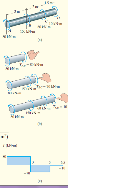
Determine the angle of twist of the end A of the A-36 steel shaft shown in Fig.a. Also, what is the angle of twist of A relative to C? The shaft has a diameter of 200 mm.

Transcribed Image Text:1.5 m
2 m
3 m
10 kN-m
B.
60 kN-m
150 kN-m
80 kN-m
(a)
TAB = 80 kN-m
80 kN-m
150 kN-m
Твс — 70 kN-m
80 kN-m
60 kN-m TcD = 10
150 kN-m
80 kN-m
(b)
m?)
T (kN-m)
80
6.5
-10
-70
(c)
en
Expert Solution
This question has been solved!
Explore an expertly crafted, step-by-step solution for a thorough understanding of key concepts.
Step by stepSolved in 2 steps with 1 images

Knowledge Booster
Learn more about
Need a deep-dive on the concept behind this application? Look no further. Learn more about this topic, mechanical-engineering and related others by exploring similar questions and additional content below.Similar questions
- A 48 inches diameter saw blade is mounted on a pulley driven steel shaft, requiring a blade peripheral linear speed of 150 ft./sec. Motor drive is 125 Hp at 1,200 rpm, with 6 inches diameter pulley, determine the shaft diameter. Consider allowable shearing stress of 5000 psi O a. 2 in O b.3 in O C. 4 in O d. 5 inarrow_forwardplease help solvearrow_forwardPLEASE ANSWER NUMBER 2 MECH 222: PLEASE GIVE DETAILED SOLUTIONS AND CORRECT ANSWERS. I WILL REPORT TO BARTLEBY THOSE TUTORS WHO WILL GIVE INCORRECT ANSWERS.arrow_forward
- 20. Determine the angle of twist of the end A of theA-36 steel shaft shown in Fig. 10-16a. Also, what is the angle of twist of A relative to C? The shaft has a diameter of 200 mm. 1.5 m 3 m A 80 kN.m 2 m |В 150 kN.m D 10 kN.m C 60 kN.marrow_forward64. A solid circular shaft of diameter d and length L is fixed at one end and free at the other end. A torque t is applied at the free end. The shear modulus of the material is G. The angle of twist at three free ends is O A. O B. O C. O D. 16TL Td4G 32TL πd4G 64TL Td4G 128TL πd4Garrow_forwardQUESTION 20 A compound shaft consists of a solid rod of diameter D and a sleeve of diameter 2D of the same material firmly fixed together by a key. The compound shaft is subjected to a torque of 100 kNm. Key Bushing Shaft Oa. The torque carried by the rod and the sleeve are 50 kNm each. Ob. The torque carried by the rod and the sleeve are 100 kNm each. Oc. The entire torque of 100 kNm is carried by the outer sleeve only. O d. None of the above answers.arrow_forward
- A motor is used to drive a gear assembly at 200 rpm. The main gear is in the center of a 1 m long (0.5 m to the left and right of the gear) 50 mm diameter solid circular shaft, and power is taken from the two shaft ends. 25 kW is taken on the left end and an unknown amount of power is taken at the right end. the torque to the left side of the gear is? maximum shear stress to left of gear? If the maximum shear stress on the shaft to the right of the gear is 125 MPa, approximately how much power is being drawn off from the right side of the shaft? The shaft can be made from 6061-T6 aluminum. It has adequate strength to withstand the loading conditions in the scenario, including the loading on the right side of the shaft. true or false?arrow_forwardPlease don't provide handwritten solution ......arrow_forwardA shaft is 21/2 in. square, and the allowable shearing unit stress for the material is 6000 psi. The torque on the shaft is A. 27,600 in B 20,800 in C. 31,200 in D. 24,100 inarrow_forward
- A steel shaft 2542 mm long must transmit a torque of 34 KN-m. The total angle of twist and the maximum shearing stress must not exceed 3 degree and 110 MPa respectively. Find the diameter of the shaft that meets there conditions. Check based on strength and rigidity. Use G = 78268 MPa. Use two (2) decimal places.arrow_forwardFor the steel shaft shown in Fig. Draw a torque diagram for the shaft. 17 ft kip 60 ft-kip 12 ft-kip 10 ft-kip 25 ft-kiparrow_forwardNeed only handwritten solution only (not typed one).arrow_forward
arrow_back_ios
arrow_forward_ios
Recommended textbooks for you
 Elements Of ElectromagneticsMechanical EngineeringISBN:9780190698614Author:Sadiku, Matthew N. O.Publisher:Oxford University Press
 Mechanics of Materials (10th Edition)Mechanical EngineeringISBN:9780134319650Author:Russell C. HibbelerPublisher:PEARSON
 Thermodynamics: An Engineering ApproachMechanical EngineeringISBN:9781259822674Author:Yunus A. Cengel Dr., Michael A. BolesPublisher:McGraw-Hill Education
 Control Systems EngineeringMechanical EngineeringISBN:9781118170519Author:Norman S. NisePublisher:WILEY
 Mechanics of Materials (MindTap Course List)Mechanical EngineeringISBN:9781337093347Author:Barry J. Goodno, James M. GerePublisher:Cengage Learning
 Engineering Mechanics: StaticsMechanical EngineeringISBN:9781118807330Author:James L. Meriam, L. G. Kraige, J. N. BoltonPublisher:WILEY

Elements Of Electromagnetics
Mechanical Engineering
ISBN:9780190698614
Author:Sadiku, Matthew N. O.
Publisher:Oxford University Press

Mechanics of Materials (10th Edition)
Mechanical Engineering
ISBN:9780134319650
Author:Russell C. Hibbeler
Publisher:PEARSON

Thermodynamics: An Engineering Approach
Mechanical Engineering
ISBN:9781259822674
Author:Yunus A. Cengel Dr., Michael A. Boles
Publisher:McGraw-Hill Education

Control Systems Engineering
Mechanical Engineering
ISBN:9781118170519
Author:Norman S. Nise
Publisher:WILEY

Mechanics of Materials (MindTap Course List)
Mechanical Engineering
ISBN:9781337093347
Author:Barry J. Goodno, James M. Gere
Publisher:Cengage Learning

Engineering Mechanics: Statics
Mechanical Engineering
ISBN:9781118807330
Author:James L. Meriam, L. G. Kraige, J. N. Bolton
Publisher:WILEY