
Introductory Circuit Analysis (13th Edition)
13th Edition
ISBN: 9780133923605
Author: Robert L. Boylestad
Publisher: PEARSON
expand_more
expand_more
format_list_bulleted
Related questions
Concept explainers
Question
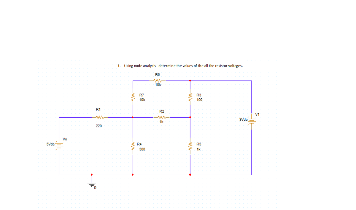

Transcribed Image Text:**Circuit Analysis Using Node Method**
**Objective:**
Determine the values of all the resistor voltages using node analysis.
**Circuit Description:**
In the diagram, we have a complex circuit with the following components and connections:
1. **Voltage Sources:**
- **5V DC Source**: On the left side, connected to resistor \( R_1 \).
- **9V DC Source**: On the right side, labeled as \( V_1 \).
2. **Resistors:**
- \( R_1 \): 220 Ohms, connected between the 5V source and the first node.
- \( R_2 \): 1k Ohm, connected in series between Nodes 1 and 2.
- \( R_3 \): 100 Ohms, connected in parallel from Node 2 to the \( V_1 \) source.
- \( R_4 \): 500 Ohms, connected in parallel from the ground to Node 1.
- \( R_5 \): 1k Ohm, connected from Node 2 to Node 3.
- \( R_6 \): Not present in the diagram despite typical mention in sequences.
- \( R_7 \) and \( R_8 \): Both 10k Ohms, connected in series from Node 1 to Node 2.
3. **Ground Connection:**
- Present at the base, providing a common reference point.
**Procedure:**
Using node analysis, apply the following steps:
1. Identify and label each node.
2. Apply Kirchhoff's Current Law (KCL) to each node (except the reference node).
3. Set up and solve the resulting system of equations to find the node voltages.
4. Use the node voltages to calculate the voltage across each resistor.
**Graph/Diagram Explanation:**
- The circuit is shown with nodes designated by red dots. The components are connected with straight lines representing wires.
- The diagram includes the necessary values for each resistor and voltage source to perform calculations.
By following these steps, one can accurately determine the voltage across each resistor, facilitating an understanding of the circuit dynamics through node analysis.
Expert Solution
This question has been solved!
Explore an expertly crafted, step-by-step solution for a thorough understanding of key concepts.

Step by stepSolved in 3 steps with 3 images

Knowledge Booster


Learn more about
Need a deep-dive on the concept behind this application? Look no further. Learn more about this topic, electrical-engineering and related others by exploring similar questions and additional content below.Similar questions
Recommended textbooks for you
- Introductory Circuit Analysis (13th Edition)Electrical EngineeringISBN:9780133923605Author:Robert L. BoylestadPublisher:PEARSON
 Delmar's Standard Textbook Of ElectricityElectrical EngineeringISBN:9781337900348Author:Stephen L. HermanPublisher:Cengage Learning
 Programmable Logic ControllersElectrical EngineeringISBN:9780073373843Author:Frank D. PetruzellaPublisher:McGraw-Hill Education
  Fundamentals of Electric CircuitsElectrical EngineeringISBN:9780078028229Author:Charles K Alexander, Matthew SadikuPublisher:McGraw-Hill Education
 Electric Circuits. (11th Edition)Electrical EngineeringISBN:9780134746968Author:James W. Nilsson, Susan RiedelPublisher:PEARSON
 Engineering ElectromagneticsElectrical EngineeringISBN:9780078028151Author:Hayt, William H. (william Hart), Jr, BUCK, John A.Publisher:Mcgraw-hill Education,
Introductory Circuit Analysis (13th Edition)
Electrical Engineering
ISBN:9780133923605
Author:Robert L. Boylestad
Publisher:PEARSON
Delmar's Standard Textbook Of Electricity
Electrical Engineering
ISBN:9781337900348
Author:Stephen L. Herman
Publisher:Cengage Learning
Programmable Logic Controllers
Electrical Engineering
ISBN:9780073373843
Author:Frank D. Petruzella
Publisher:McGraw-Hill Education
Fundamentals of Electric Circuits
Electrical Engineering
ISBN:9780078028229
Author:Charles K Alexander, Matthew Sadiku
Publisher:McGraw-Hill Education
Electric Circuits. (11th Edition)
Electrical Engineering
ISBN:9780134746968
Author:James W. Nilsson, Susan Riedel
Publisher:PEARSON
Engineering Electromagnetics
Electrical Engineering
ISBN:9780078028151
Author:Hayt, William H. (william Hart), Jr, BUCK, John A.
Publisher:Mcgraw-hill Education,