
Introductory Circuit Analysis (13th Edition)
13th Edition
ISBN: 9780133923605
Author: Robert L. Boylestad
Publisher: PEARSON
expand_more
expand_more
format_list_bulleted
Related questions
Concept explainers
Question
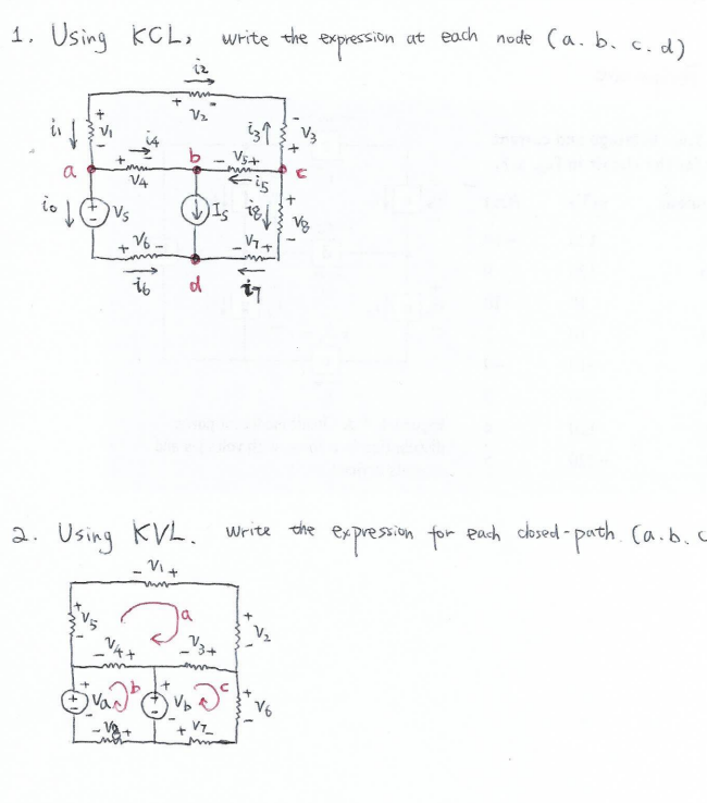

Transcribed Image Text:### Electrical Circuit Analysis using Kirchhoff's Laws
#### 1. Kirchhoff's Current Law (KCL)
Using KCL, we write the expression for the current at each node (a, b, c, d).
**Circuit Diagram Overview:**
The circuit shown includes the following components:
- Several resistors and voltage sources.
- Nodes labeled as a, b, c, d.
- Various currents labeled \( i_1, i_2, i_3, i_4, i_5, i_6, i_7 \).
- Voltage sources labeled \( V_1, V_2, V_3, V_4, V_5, V_6, V_7 \).
- A current source labeled \( I_S \).
**1. Nodes Description:**
- **Node a:** Intersection of \( i_0, i_1, i_4, \) and the voltage source \( V_1 \).
- **Node b:** Intersection of \( i_1, i_2, i_5, I_S \), and the voltage source \( V_4 \).
- **Node c:** Intersection of \( i_3, i_5, i_6 \), and the voltage source \( V_6 \).
- **Node d:** Intersection of \( i_6, i_7, \) and the voltage source \( V_7 \).
---
#### 2. Kirchhoff's Voltage Law (KVL)
Using KVL, write the expression for the voltage around each closed path (a, b, c).
**Circuit Diagram Overview:**
1. **Loop a**:
- Contains voltage sources \( -V_1 \), \( V_5 \), \( V_4 \)
- Contains resistors \( R_1, R_2 \)
2. **Loop b**:
- Contains voltage sources \( V_3 \), \( V_2 \)
- Contains resistors \( R_3, R_4 \)
3. **Loop c**:
- Contains voltage sources \( -V_6 \), \( -V_7 \)
- Contains resistors \( R_5, R_6 \)
---
This information can be utilized for educational purposes to teach Kirchhoff's Circuit Laws in an Electrical Engineering curriculum. Understanding the principles of KCL and KVL is fundamental for the analysis and design of electronic circuits.
Expert Solution
This question has been solved!
Explore an expertly crafted, step-by-step solution for a thorough understanding of key concepts.

This is a popular solution

Trending nowThis is a popular solution!

Step by stepSolved in 2 steps with 2 images

Knowledge Booster


Learn more about
Need a deep-dive on the concept behind this application? Look no further. Learn more about this topic, electrical-engineering and related others by exploring similar questions and additional content below.Similar questions
- Peak input voltage =(from graph) ?Peak output voltage = (from graph)?DC voltage across RL = ?ripple factor=?arrow_forwardQ2) determine A>B, Aarrow_forwardThe shown sequential circuit has a single input X and three output Q2Q1Q0. Note: As shown in the figure, all D-FFs are equipped with asynchronous set (SET) and clear (CLR) inputs. 011 Part (a). Analyse the circuit and derive its state table? Is the circuit Moore or Mealy? Q2 Qi Qo 2x1 Mих Part (b). The circuit should have an asynchronous reset input, which puts the circuit in initial state 010. Show how this can be done? Cout 3-bit Cin Part (c). Briefly describe the function of this Adder circuit. S2 10 D. Q CLR Q D, Q CLR Q. CLR Clkarrow_forward
Recommended textbooks for you
- Introductory Circuit Analysis (13th Edition)Electrical EngineeringISBN:9780133923605Author:Robert L. BoylestadPublisher:PEARSON
 Delmar's Standard Textbook Of ElectricityElectrical EngineeringISBN:9781337900348Author:Stephen L. HermanPublisher:Cengage Learning
 Programmable Logic ControllersElectrical EngineeringISBN:9780073373843Author:Frank D. PetruzellaPublisher:McGraw-Hill Education
  Fundamentals of Electric CircuitsElectrical EngineeringISBN:9780078028229Author:Charles K Alexander, Matthew SadikuPublisher:McGraw-Hill Education
 Electric Circuits. (11th Edition)Electrical EngineeringISBN:9780134746968Author:James W. Nilsson, Susan RiedelPublisher:PEARSON
 Engineering ElectromagneticsElectrical EngineeringISBN:9780078028151Author:Hayt, William H. (william Hart), Jr, BUCK, John A.Publisher:Mcgraw-hill Education,
Introductory Circuit Analysis (13th Edition)
Electrical Engineering
ISBN:9780133923605
Author:Robert L. Boylestad
Publisher:PEARSON
Delmar's Standard Textbook Of Electricity
Electrical Engineering
ISBN:9781337900348
Author:Stephen L. Herman
Publisher:Cengage Learning
Programmable Logic Controllers
Electrical Engineering
ISBN:9780073373843
Author:Frank D. Petruzella
Publisher:McGraw-Hill Education
Fundamentals of Electric Circuits
Electrical Engineering
ISBN:9780078028229
Author:Charles K Alexander, Matthew Sadiku
Publisher:McGraw-Hill Education
Electric Circuits. (11th Edition)
Electrical Engineering
ISBN:9780134746968
Author:James W. Nilsson, Susan Riedel
Publisher:PEARSON
Engineering Electromagnetics
Electrical Engineering
ISBN:9780078028151
Author:Hayt, William H. (william Hart), Jr, BUCK, John A.
Publisher:Mcgraw-hill Education,