
Introductory Circuit Analysis (13th Edition)
13th Edition
ISBN: 9780133923605
Author: Robert L. Boylestad
Publisher: PEARSON
expand_more
expand_more
format_list_bulleted
Related questions
Question
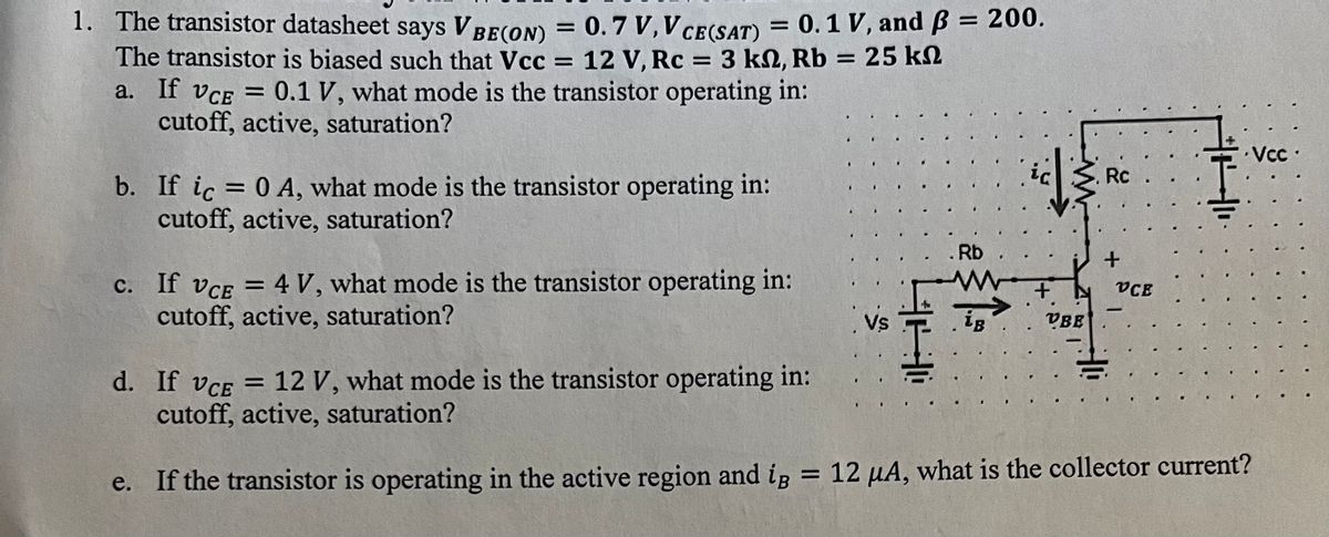

Transcribed Image Text:1. The transistor datasheet says VBE(ON) = 0.7 V, V CE(SAT) = 0.1 V, and ß = 200.
The transistor is biased such that Vcc = 12 V, Rc = 3 kn, Rb = 25 kn
a. If VCE = 0.1 V, what mode is the transistor operating in:
cutoff, active, saturation?
ΚΩ
b. If ic = 0 A, what mode is the transistor operating in:
cutoff, active, saturation?
c. If VCE = 4 V, what mode is the transistor operating in:
cutoff, active, saturation?
1
S..
VS
Rb
F
He
1.
+
VBE
Rc
+
VCE
-
d. If VCE = 12 V, what mode is the transistor operating in:
cutoff, active, saturation?
e. If the transistor is operating in the active region and ig = 12 µA, what is the collector current?
Vcc.
Expert Solution
This question has been solved!
Explore an expertly crafted, step-by-step solution for a thorough understanding of key concepts.

This is a popular solution

Trending nowThis is a popular solution!

Step by stepSolved in 3 steps with 2 images

Knowledge Booster


Learn more about
Need a deep-dive on the concept behind this application? Look no further. Learn more about this topic, electrical-engineering and related others by exploring similar questions and additional content below.Similar questions
- A base bias method is used in the following circuit. For Bpc - 300, the value of emitter current is: -Vc. +15 V Rc 1.8 k2 RB 560 k2 7.82 mA O 6.84 mA O 7.27 mAarrow_forwardWhat is the Q-point for a biased transistor as in Figure F with Ig = 70μA, BDC 110, Vcc = 24V, and Rc = 3k2. 3kohm Rc= 01 Vout 2N2222A RB w IB = 70μΑ BDC= 110 VBB Figure F Vcc = 24Varrow_forwardThe parameters of the transistor in the figure below are ß = 100 and Vy = 0.7 V. Find iç and Vea for Vs = 0.8V. Repeat for Vs =2.5V. 10 k. ic + 10 ΚΩ VCE 20 k2 15 V iB vsarrow_forward
- Determine the collector current in mA and determine what mode is the transistor for circuit belowarrow_forwardAssume VRE 0.7 V and B-50 for the transistor in the circuit shown in the figure. For VCE = 2 V, the value of Rg is RB m B +12 V www Rc- 5 k C E VCEarrow_forwardThe transistor shown in the crout below has a oument gain of p-100. You may assume the voltage between the base and the emer is 0.7V Calculate the collector voltage V 1820 ΚΩ b 3.5k Vc=? 20 9Varrow_forward
- Vec +12V Re 1kS2 Re 470k2 BC107 Vc Ve Figure 3: Practical Fixed Bias Transistor Circuit 2. Measure the DC voltages Vc and VB using digital multi-meters. Determine the quiescent base current, collector current, and collector- emitter voltage.arrow_forwardFor the circuit shown below, assume that ß = 240, Va = 120V and VT = .025V. a) Determine the small signal parameters for the transistor. Show your work! b) Draw the small signal model Vin www 408K 80K 12V m 35K 2K 30K 0.4mA VoQ = 5Varrow_forwardPlease answer ASAP. I will rate Positivelyarrow_forward
- Solve the collector-emitter voltage (VCE) of Figure 612. vc 8V R1 3.3ka Beta = 110 VEE R2 -12V 3.9ka Figure 612 1.48V O -0.7V O - 0.86V O 0.7Varrow_forward3. Design a four-resistor BJT bias circuit, similar to the one shown in Figure 2, such that V3 = 4 V and Ic = 1 mA. Assume VBE (on) = 0.7 V and B-150 for the transistor. 12V R1 R2 10k RC 5.6k Q2N2222 RE Figure 2 Note: Use PN2222A in Multisimarrow_forwardDetermine thel 1.V B, c and V for the transistor circuit in Figure. Rc 430 Q Rg Vcc A) Poc = 50 24 V 4.7 ko VBB 2 Varrow_forward
arrow_back_ios
SEE MORE QUESTIONS
arrow_forward_ios
Recommended textbooks for you
- Introductory Circuit Analysis (13th Edition)Electrical EngineeringISBN:9780133923605Author:Robert L. BoylestadPublisher:PEARSON
 Delmar's Standard Textbook Of ElectricityElectrical EngineeringISBN:9781337900348Author:Stephen L. HermanPublisher:Cengage Learning
 Programmable Logic ControllersElectrical EngineeringISBN:9780073373843Author:Frank D. PetruzellaPublisher:McGraw-Hill Education
  Fundamentals of Electric CircuitsElectrical EngineeringISBN:9780078028229Author:Charles K Alexander, Matthew SadikuPublisher:McGraw-Hill Education
 Electric Circuits. (11th Edition)Electrical EngineeringISBN:9780134746968Author:James W. Nilsson, Susan RiedelPublisher:PEARSON
 Engineering ElectromagneticsElectrical EngineeringISBN:9780078028151Author:Hayt, William H. (william Hart), Jr, BUCK, John A.Publisher:Mcgraw-hill Education,
Introductory Circuit Analysis (13th Edition)
Electrical Engineering
ISBN:9780133923605
Author:Robert L. Boylestad
Publisher:PEARSON
Delmar's Standard Textbook Of Electricity
Electrical Engineering
ISBN:9781337900348
Author:Stephen L. Herman
Publisher:Cengage Learning
Programmable Logic Controllers
Electrical Engineering
ISBN:9780073373843
Author:Frank D. Petruzella
Publisher:McGraw-Hill Education
Fundamentals of Electric Circuits
Electrical Engineering
ISBN:9780078028229
Author:Charles K Alexander, Matthew Sadiku
Publisher:McGraw-Hill Education
Electric Circuits. (11th Edition)
Electrical Engineering
ISBN:9780134746968
Author:James W. Nilsson, Susan Riedel
Publisher:PEARSON
Engineering Electromagnetics
Electrical Engineering
ISBN:9780078028151
Author:Hayt, William H. (william Hart), Jr, BUCK, John A.
Publisher:Mcgraw-hill Education,