Introductory Circuit Analysis (13th Edition)
13th Edition
ISBN: 9780133923605
Author: Robert L. Boylestad
Publisher: PEARSON
expand_more
expand_more
format_list_bulleted
Question

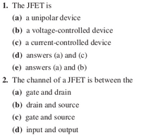
Transcribed Image Text:1. The JFET is
(a) a unipolar device
(b) a voltage-controlled device
(c) a current-controlled device
(d) answers (a) and (c)
(e) answers (a) and (b)
2. The channel of a JFET is between the
(a) gate and drain
(b) drain and source
(c) gate and source
(d) input and output
Expert Solution
This question has been solved!
Explore an expertly crafted, step-by-step solution for a thorough understanding of key concepts.
This is a popular solution
Trending nowThis is a popular solution!
Step by stepSolved in 2 steps

Knowledge Booster
Learn more about
Need a deep-dive on the concept behind this application? Look no further. Learn more about this topic, electrical-engineering and related others by exploring similar questions and additional content below.Similar questions
- Collector characteristics for the Ge transistor If VEE =2 V, VCC =12V, and RC = 2k , size RE so that VCEQ = 6.4V. io mA ig-7 mA 6 mA 5 mA 4 mA Aic for hys Aig for he 3 mA Aic for hab Avea for h 2 mA I mA -10 -12 14 -16 -1- -20 "Carrow_forwardWhat will happen to the output if the diode D1 gets damaged and gets open (ideal diode) D ZR, none of the above half of ac input at output full ac input at output no output voltagearrow_forwardExplain diagramarrow_forward
- Figure below shows a 4-input OR gate built using a chain of gates. Determine the activity factors at each node in the circuit assuming the input probabilities PA= PB = Pc = PD=0.5. C D an am P = am Domz an am ng aarrow_forwardQ4-What is the fire angle that required to design an R-triggering circuit for a half wave controlled rectifier for SCR, the following parameters are applicable Ig(min) = 0.5mA, Vgt(min) 50HZ „Resistance in gate current path = 60 k2. 0.7V, Vd=0.7V, Supply voltage = 30 V, LOAD R VsVsinot strical Pow Dept II >arrow_forwardcuicuit designed in winknown isubuenit, va resistance R = 2.8K2 and two identical silicon BITS T1 and 12 with 72 and T2 with forward gains BF = 200. The supply voltage Vcc =-25 volts Vcc=25 volts Sub-circuit JICA T2 IB₁1 IB12 VIR R = 28K2 VIC, 2 GIND IB, 1 and Ic, s designate the base and collector current of T2 vespectively where as the courrents IB,₁2 and IG2 designate the base and the collector currents of T2 respectively. T2 and 12 operate in forward active mode Assume that IB, 1 and IB₁2 are equal · VBE, on = 0.8 molt (Threshold woltage) (a) What is the value of the current IR through vesistance R.? (MA) (b) what is the value of the base vaurrent IB, 1? (MA) (c) what is the value of the collector Ic₁₁? (MA) (d) The evicuit idesigned using Resistance Rand Transistors T₁ and To performs an electronic function to connect to sub circut which function is it?arrow_forward
- (Asterisked problems are associated with optional sections.) 1. Determine the output of each of the following circuits, assuming that the upper input is 1 and the lower input is 0. What would be the output when the upper input is 0 and the lower input is 1? a. b. C. D D nia 00arrow_forwardQuestion 3 The 555 timer is connected in the following circuit. The resistance of the extra resistor is 102, the capacitance of the extra capacitor is 0.1F. The voltage input at Pin2 is Vcc. What is the output state at Pin3? 1) 2) Decide the voltage input value at Pin 6 when the condition is stable. 3) Decide the output state at Pin3 when a trigger input is applied at Pin2 (voltage input at Pin2 changes from Vcc to 0, and return back to Vcc immediately). 4) After the trigger input is applied at Pin2, how long would the output maintain at the unstable state. Vc R O Output Vo 555 Vc 0.01µF Trigger Inputarrow_forward
arrow_back_ios
arrow_forward_ios
Recommended textbooks for you
 Introductory Circuit Analysis (13th Edition)Electrical EngineeringISBN:9780133923605Author:Robert L. BoylestadPublisher:PEARSON
 Delmar's Standard Textbook Of ElectricityElectrical EngineeringISBN:9781337900348Author:Stephen L. HermanPublisher:Cengage Learning
 Programmable Logic ControllersElectrical EngineeringISBN:9780073373843Author:Frank D. PetruzellaPublisher:McGraw-Hill Education
 Fundamentals of Electric CircuitsElectrical EngineeringISBN:9780078028229Author:Charles K Alexander, Matthew SadikuPublisher:McGraw-Hill Education
 Electric Circuits. (11th Edition)Electrical EngineeringISBN:9780134746968Author:James W. Nilsson, Susan RiedelPublisher:PEARSON
 Engineering ElectromagneticsElectrical EngineeringISBN:9780078028151Author:Hayt, William H. (william Hart), Jr, BUCK, John A.Publisher:Mcgraw-hill Education,

Introductory Circuit Analysis (13th Edition)
Electrical Engineering
ISBN:9780133923605
Author:Robert L. Boylestad
Publisher:PEARSON

Delmar's Standard Textbook Of Electricity
Electrical Engineering
ISBN:9781337900348
Author:Stephen L. Herman
Publisher:Cengage Learning

Programmable Logic Controllers
Electrical Engineering
ISBN:9780073373843
Author:Frank D. Petruzella
Publisher:McGraw-Hill Education

Fundamentals of Electric Circuits
Electrical Engineering
ISBN:9780078028229
Author:Charles K Alexander, Matthew Sadiku
Publisher:McGraw-Hill Education

Electric Circuits. (11th Edition)
Electrical Engineering
ISBN:9780134746968
Author:James W. Nilsson, Susan Riedel
Publisher:PEARSON

Engineering Electromagnetics
Electrical Engineering
ISBN:9780078028151
Author:Hayt, William H. (william Hart), Jr, BUCK, John A.
Publisher:Mcgraw-hill Education,