Introductory Circuit Analysis (13th Edition)
13th Edition
ISBN: 9780133923605
Author: Robert L. Boylestad
Publisher: PEARSON
expand_more
expand_more
format_list_bulleted
Question

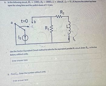
Transcribed Image Text:1. In the following circuit, R₁ = 1000, R₂ =2000, L=10mH,Is=0.1 A.Assume the switch has been
open for a long time and the switch closes at t=0 sec.
Fo
t=0
Is
Enter answer here
A
R₁
Use the Norton Equivalent Circuit method to solve for the equivalent parallel RL circuit. Enter Re, in the box
below, without units.
Enter answer here
2. Find I Enter the number without units.
R₂
Expert Solution
This question has been solved!
Explore an expertly crafted, step-by-step solution for a thorough understanding of key concepts.
Step by stepSolved in 3 steps with 2 images

Knowledge Booster
Similar questions
- Full solution Required along with the** PHASOR DIAGRAM** PHASOR DIAGRAM IS A MUSTarrow_forwardCharacteristic equation of a system is given below. -5s6-2s5- 10s1-9s3-2s2-4s – 10=0 .Which of the following statement is correct? Oall the coefficients are negative. Hence we can conclude that system is stable. Necessary condition of RH criteria is satisfied. Sufficient condition has to be checked with RH table. Necessary condition of RH criteria is not satisfied. Hence system is unstable O all the coefficients are negative. Hence we can conclude that system is unstable.arrow_forwardFor the circuit given in fiqure 6, find V_ rms and ms on R3. R, R3 10 20 R2 RA 5 Vp Figure 6arrow_forward
- Q.2: Solve the following determinate. Then, simplify the complex numbers to find x and y values (the separated real and imaginary value). (Note: Check the answer by the caleulator) 18 - 6i 5230 2i V- -3i 3 - 4iarrow_forwardQ25) please answer quiclyarrow_forwardVR C R E An R-C series circuit consists of a capacitor with capacitance, C, connected in series with a resistor with resistance, R. The resistance, R, is a circuit parameter that opposes the amount of electric charges Q, passing through the circuit per unit time and causes a drop in potential given by Ohm's Law while the capacitance, C, is a circuit parameter that measures the amount of electric charges that the current carries and stores in the capacitor. Both the resistor and capacitor cause the total drop in electric potential and is equivalent to the total electromotive force, E, which is produced by a voltage source such as batteries. E=+Rat As soon as the switch is opened, the initial charge Q, that is stored in the capacitor varies through time, t. In the given differential equation above, the charge Q and the time t are the dependent and independent variables, respectively. The electromotive force E, the resistance R, and the capacitance C are constants. Using A as the constant…arrow_forward
- In order to get the step 4 the full yellow paper will be the guide to find the step 4. STEP 1: Current Loops STEP 2: Remove Integrals STEP 3: Simplify STEP 4: ? Note: THE YELLOW FULL PAPER HAVE A DIFFERENT GIVEN YOU WILL JUST USE THIS AS A GUIDE OR REFERENCES HOW TO SOLVE THE STEP 4:arrow_forwardplease choose one of these snswers thank you thevsteady equilibrium current that exists in the inductor is nearly 2.5A 2.27A 1.36A 0.91A In the given circuit, the inductor (L-5 H) and a 50-V battery of negligible resistance are connected with resistors R 10 W and R2 30 w, and Rg 20 Ww as shown. The switch was closed at t 0 and kept closed for a long time until a steady equilibrium current existed.arrow_forwardShown in the figure below is an electrical circuit containing three resistors and two batteries. R3 10 R2 R1 Write down the Kirchhoff Junction equation and solve it for I, in terms of I, and Iz. Write the result here: Write down the Kirchhoff Loop equation for a loop that starts at the lower left corner and follows the perimeter of the circuit diagram clockwise. Write down the Kirchhoff Loop equation for a loop that starts at the lower left corner and touches the components R1, R2, and 4V. The resistors in the circuit have the following values: R, = 130 • R2 = 50 R3 = 10 Solve for all the following (some answers may be negative): | Amperes I = I, = Amperes Iz = Amperes NOTE: For the equations, put in resistances and currents SYMBOLICALLY using variables like RR2,R3 and I,,12,13. Use numerical values of 10 and 4 for the voltages.arrow_forward
- RI=102 E-2IV- R2 =150 %3D BY THEVENINS THEOREM SOLVE FOR (A.)RTH (B.) VTHarrow_forwardChoose the correct answer among the choices. Show solution.arrow_forward20 For the circuit shown in the figure next, Rth (seen by the left side of RL) is found to be (in Ohms) v, 4n Figure X1 None of the choices O 24arrow_forward
arrow_back_ios
arrow_forward_ios
Recommended textbooks for you
 Introductory Circuit Analysis (13th Edition)Electrical EngineeringISBN:9780133923605Author:Robert L. BoylestadPublisher:PEARSON
 Delmar's Standard Textbook Of ElectricityElectrical EngineeringISBN:9781337900348Author:Stephen L. HermanPublisher:Cengage Learning
 Programmable Logic ControllersElectrical EngineeringISBN:9780073373843Author:Frank D. PetruzellaPublisher:McGraw-Hill Education
 Fundamentals of Electric CircuitsElectrical EngineeringISBN:9780078028229Author:Charles K Alexander, Matthew SadikuPublisher:McGraw-Hill Education
 Electric Circuits. (11th Edition)Electrical EngineeringISBN:9780134746968Author:James W. Nilsson, Susan RiedelPublisher:PEARSON
 Engineering ElectromagneticsElectrical EngineeringISBN:9780078028151Author:Hayt, William H. (william Hart), Jr, BUCK, John A.Publisher:Mcgraw-hill Education,

Introductory Circuit Analysis (13th Edition)
Electrical Engineering
ISBN:9780133923605
Author:Robert L. Boylestad
Publisher:PEARSON

Delmar's Standard Textbook Of Electricity
Electrical Engineering
ISBN:9781337900348
Author:Stephen L. Herman
Publisher:Cengage Learning

Programmable Logic Controllers
Electrical Engineering
ISBN:9780073373843
Author:Frank D. Petruzella
Publisher:McGraw-Hill Education

Fundamentals of Electric Circuits
Electrical Engineering
ISBN:9780078028229
Author:Charles K Alexander, Matthew Sadiku
Publisher:McGraw-Hill Education

Electric Circuits. (11th Edition)
Electrical Engineering
ISBN:9780134746968
Author:James W. Nilsson, Susan Riedel
Publisher:PEARSON

Engineering Electromagnetics
Electrical Engineering
ISBN:9780078028151
Author:Hayt, William H. (william Hart), Jr, BUCK, John A.
Publisher:Mcgraw-hill Education,