Introductory Circuit Analysis (13th Edition)
13th Edition
ISBN: 9780133923605
Author: Robert L. Boylestad
Publisher: PEARSON
expand_more
expand_more
format_list_bulleted
Concept explainers
Question
thumb_up100%

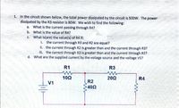
Transcribed Image Text:1. In the circuit shown below, the total power dissipated by the circuit is 500W. The power
dissipated by the R3 resistor is 80W. We wish to find the following:
a. What is the current passing through R4?
b. What is the value of R4?
C. What is(are) the value(s) of R4 if:
i. the current through R3 and R2 are equal?
ii. the current through R2 is greater than and the current through R3?
iii. the current through R3 is greater than and the current through R2?
d. What are the supplied current by the voltage source and the voltage V1?
R1
R3
10Ω
202
R4
R2
402
V1
Expert Solution
This question has been solved!
Explore an expertly crafted, step-by-step solution for a thorough understanding of key concepts.
Step by stepSolved in 3 steps with 3 images

Knowledge Booster
Learn more about
Need a deep-dive on the concept behind this application? Look no further. Learn more about this topic, electrical-engineering and related others by exploring similar questions and additional content below.Similar questions
- I did a physics lab and got some values. I want to check them theoretically to see how the results differ. From this diagram, answer the following questions: The laws to be verified included the conservation of current in a node, the addition of potentials for components in series, and the addition of currents for components in parallel. The data : R1: 1094 ohm R2 : 998 ohm R3: 1094 ohmR4: 25 ohm Source 1 : 5 V Source 2 : 1.5 Varrow_forwardDetermine the current of the circuit below. Then apply Ohm's law to determine the expected voltage drops across R1, R2, and R3. Record these values. Include demonstration of Kirchhoff's Voltage Law. R1 1k 9Vdc R2 220 R3 10karrow_forwardWrite the voltage node equations needed to find the six voltage nodes (a) to (f). Do not simplify. Make sure to make reference to the figure.arrow_forward
- The figure below shows the resistors wired in a different way-a combination of series and parallel. We can consider R₁, to be the resistance of wires leading to R₂ and R³ a. Find the total resistance. b. What is the IR drop in R₁? c. Find the current I through R₂. d. What power is dissipated by R₂?arrow_forwardPlease answer in typing formatarrow_forwardResistors Circuits I Each of the circuits below consists of a battery and several resistors. Several of the voltages, currents, and resistances are indicated. Use both of Kirchoff's Laws and Ohm's Law to determine as many of the other voltages, currents, and resistances as possible.arrow_forward
- Each of the cells shown in the figure has an emf of 1.50 V and a 0.0750-ohm internalresistance. Find I1, I2, and I3.arrow_forwardThe input to the circuit shown in Figure-1a is the voltage, vs. The output is the voltage vo. The voltage vb is used to adjust the relationship between the input and output. Determine values of R4 and vb that cause the circuit input and output have the relationship specified by the graph shown in Figure-1.arrow_forwardH.W For the electrical circuit shown in the figure find - :the following .The total resistance - 1 .The current through R1 -2 The power consumed by R3 -3 R3 R2 2k olun 12- 1₁ 2k olun www R1 IT E 24 V 2k olun 13- 1₁ 6k olun ww R4arrow_forward
- Find the unknown quantities for the circuits in Figure using the information provided. V=I.R P=8W R. R₁ = 169 K₂ P=4W 192 1/1arrow_forwardFor the circuit in the figure, find the following:(a) Equivalent strength(b) The current supplied by the source (total current)c) Partial currents and voltages (the current and voltage of each resistor).e) Extra: what voltage the voltmeter will measure by setting it to R1 and then R2.arrow_forward4. Source transformationarrow_forward
arrow_back_ios
SEE MORE QUESTIONS
arrow_forward_ios
Recommended textbooks for you
 Introductory Circuit Analysis (13th Edition)Electrical EngineeringISBN:9780133923605Author:Robert L. BoylestadPublisher:PEARSON
 Delmar's Standard Textbook Of ElectricityElectrical EngineeringISBN:9781337900348Author:Stephen L. HermanPublisher:Cengage Learning
 Programmable Logic ControllersElectrical EngineeringISBN:9780073373843Author:Frank D. PetruzellaPublisher:McGraw-Hill Education
 Fundamentals of Electric CircuitsElectrical EngineeringISBN:9780078028229Author:Charles K Alexander, Matthew SadikuPublisher:McGraw-Hill Education
 Electric Circuits. (11th Edition)Electrical EngineeringISBN:9780134746968Author:James W. Nilsson, Susan RiedelPublisher:PEARSON
 Engineering ElectromagneticsElectrical EngineeringISBN:9780078028151Author:Hayt, William H. (william Hart), Jr, BUCK, John A.Publisher:Mcgraw-hill Education,

Introductory Circuit Analysis (13th Edition)
Electrical Engineering
ISBN:9780133923605
Author:Robert L. Boylestad
Publisher:PEARSON

Delmar's Standard Textbook Of Electricity
Electrical Engineering
ISBN:9781337900348
Author:Stephen L. Herman
Publisher:Cengage Learning

Programmable Logic Controllers
Electrical Engineering
ISBN:9780073373843
Author:Frank D. Petruzella
Publisher:McGraw-Hill Education

Fundamentals of Electric Circuits
Electrical Engineering
ISBN:9780078028229
Author:Charles K Alexander, Matthew Sadiku
Publisher:McGraw-Hill Education

Electric Circuits. (11th Edition)
Electrical Engineering
ISBN:9780134746968
Author:James W. Nilsson, Susan Riedel
Publisher:PEARSON

Engineering Electromagnetics
Electrical Engineering
ISBN:9780078028151
Author:Hayt, William H. (william Hart), Jr, BUCK, John A.
Publisher:Mcgraw-hill Education,