
Introductory Circuit Analysis (13th Edition)
13th Edition
ISBN: 9780133923605
Author: Robert L. Boylestad
Publisher: PEARSON
expand_more
expand_more
format_list_bulleted
Question
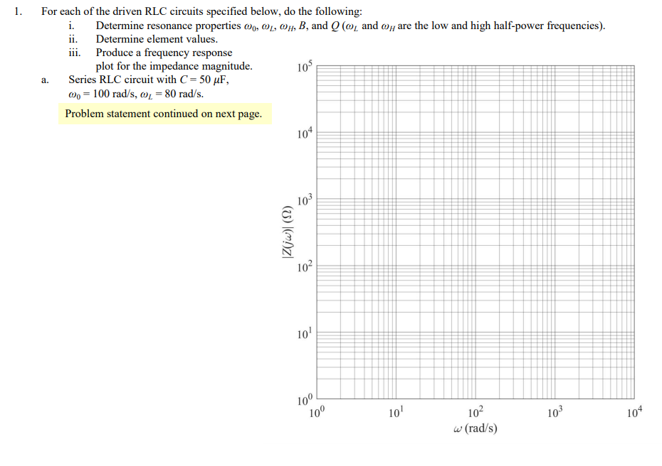
Transcribed Image Text:1.
For each of the driven RLC circuits specified below, do the following:
i.
Determine resonance properties wo, @1, Oµ, B, and Q (mį and @y are the low and high half-power frequencies).
ii. Determine element values.
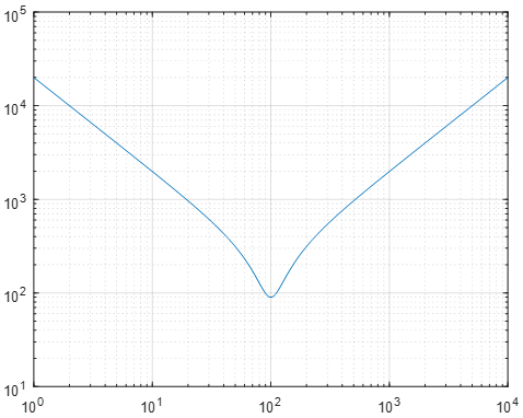
iii. Produce a frequency response
plot for the impedance magnitude.
Series RLC circuit with C= 50 µF,
wo = 100 rad/s, w = 80 rad/s.
a.
105
Problem statement continued on next page.
104
103
102
10'
10
100
10'
102
103
w (rad/s)
104
(7) |(m)Z|
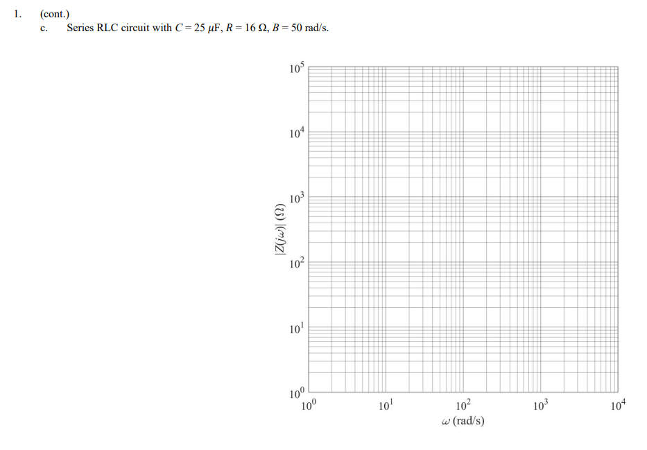
Transcribed Image Text:1.
(cont.)
Series RLC circuit with C= 25 µF, R = 16 Q, B = 50 rad/s.
c.
105
10*
10
102
10
100
10'
102
w (rad/s)
103
104
(U) |(m)Z|
Expert Solution
arrow_forward
Step 1
Part (a)
For the series RLC circuit, the given values are,
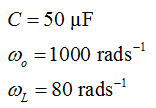
arrow_forward
Step 2
The resonance frequency is given by,

Substitute the values to evaluate the inductance,
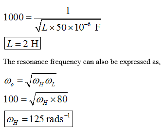
arrow_forward
Step 3
The expression of R of the circuit is,
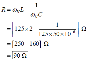
The expression of the bandwidth in the series RLC circuit is,
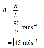
arrow_forward
Step 4
The expression of the quality factor is,
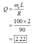
The expression of the impedance is,
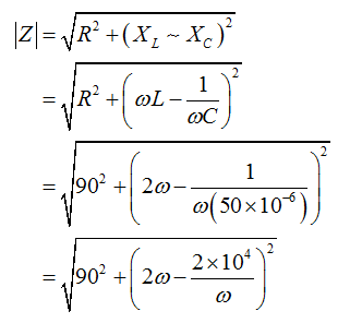
Plot the function of the impedance with the frequency.
Step by stepSolved in 7 steps with 15 images

Knowledge Booster
Similar questions
- Vi R} 3L Yo In the circuit pictured, R= 1002 L = 0.00131H C =9 × 10⁻⁶Fw= 3072.1rad/s Determine the following, a.) The value of the magnitude of when w = Orad/s b.) The value of the magnitude of when w = corad/s c.) The value of the magnitude of at the provided w. • NOTE: Enter numerical values only! Answer in base units (i.e. volts and amps). V/V is unitless. Graded as: Correct answers are within 5% of solutionsarrow_forwardGive solution in text.arrow_forward
Recommended textbooks for you
 Introductory Circuit Analysis (13th Edition)Electrical EngineeringISBN:9780133923605Author:Robert L. BoylestadPublisher:PEARSON
 Delmar's Standard Textbook Of ElectricityElectrical EngineeringISBN:9781337900348Author:Stephen L. HermanPublisher:Cengage Learning
 Programmable Logic ControllersElectrical EngineeringISBN:9780073373843Author:Frank D. PetruzellaPublisher:McGraw-Hill Education
 Fundamentals of Electric CircuitsElectrical EngineeringISBN:9780078028229Author:Charles K Alexander, Matthew SadikuPublisher:McGraw-Hill Education
 Electric Circuits. (11th Edition)Electrical EngineeringISBN:9780134746968Author:James W. Nilsson, Susan RiedelPublisher:PEARSON
 Engineering ElectromagneticsElectrical EngineeringISBN:9780078028151Author:Hayt, William H. (william Hart), Jr, BUCK, John A.Publisher:Mcgraw-hill Education,

Introductory Circuit Analysis (13th Edition)
Electrical Engineering
ISBN:9780133923605
Author:Robert L. Boylestad
Publisher:PEARSON

Delmar's Standard Textbook Of Electricity
Electrical Engineering
ISBN:9781337900348
Author:Stephen L. Herman
Publisher:Cengage Learning

Programmable Logic Controllers
Electrical Engineering
ISBN:9780073373843
Author:Frank D. Petruzella
Publisher:McGraw-Hill Education

Fundamentals of Electric Circuits
Electrical Engineering
ISBN:9780078028229
Author:Charles K Alexander, Matthew Sadiku
Publisher:McGraw-Hill Education

Electric Circuits. (11th Edition)
Electrical Engineering
ISBN:9780134746968
Author:James W. Nilsson, Susan Riedel
Publisher:PEARSON

Engineering Electromagnetics
Electrical Engineering
ISBN:9780078028151
Author:Hayt, William H. (william Hart), Jr, BUCK, John A.
Publisher:Mcgraw-hill Education,