
Database System Concepts
7th Edition
ISBN: 9780078022159
Author: Abraham Silberschatz Professor, Henry F. Korth, S. Sudarshan
Publisher: McGraw-Hill Education
expand_more
expand_more
format_list_bulleted
Related questions
Question
thumb_up100%
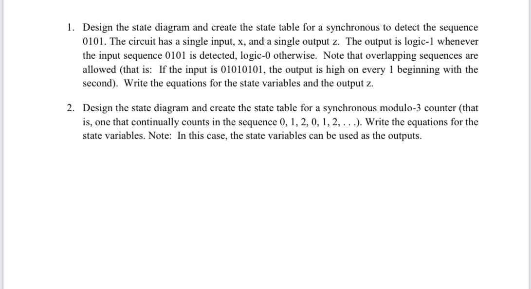

Transcribed Image Text:1. Design the state diagram and create the state table for a synchronous to detect the sequence
0101. The circuit has a single input, x, and a single output z. The output is logic-1 whenever
the input sequence 0101 is detected, logic-0 otherwise. Note that overlapping sequences are
allowed (that is: If the input is 01010101, the output is high on every 1 beginning with the
second). Write the equations for the state variables and the output z.
2. Design the state diagram and create the state table for a synchronous modulo-3 counter (that
is, one that continually counts in the sequence 0, 1, 2, 0, 1, 2, . . .). Write the equations for the
state variables. Note: In this case, the state variables can be used as the outputs.

Transcribed Image Text:1. Your goal is to design a circuit which has as input a number 0-9 represented in binary form.
The inputs are labeled A, B, C, D where A is the most significant bit. 10-15 represent "don't
care" conditions. The output is the sum of 3 and the input represented in binary form. The
outputs are labeled W, X, Y, Z where W is the most significant bit.
a. Create a truth table for the circuit.
b. Complete the Karnaugh maps for W and Y, minimizing the Boolean functions. Blank
K-maps are attached.
Write the Boolean equations for W and Y from the K-maps.
с.
2. Implement the following truth table directly (without any minimization) using a PLA. Properly
label the inputs and outputs.
Inputs
Outputs
A
C
D
X
Y
1
1
1
1
1
1
1
1
1
1
1
1
1
1
1
1
1
1
1
1
1
1
1
Expert Solution
This question has been solved!
Explore an expertly crafted, step-by-step solution for a thorough understanding of key concepts.

This is a popular solution

Trending nowThis is a popular solution!

Step by stepSolved in 2 steps with 7 images

Knowledge Booster


Learn more about
Need a deep-dive on the concept behind this application? Look no further. Learn more about this topic, computer-science and related others by exploring similar questions and additional content below.Similar questions
- 3-Write the truth table and logic equation represented by this circuit? A- ХOR B- OR AND XOR 4-Draw the logic circuit represented the following truth table. INPUT A INPUT B INPUT C OUTPUT P 1 1 1 1 1 1 1 1 1 1 5-Draw the logic circuit represented the following truth table.arrow_forward7. Given the following truth table, write an algebraic expression for the function F, simplify the expression, and then draw a logic circuit for it. A C F 1 1 1 1 1 1 1 1 1 1 1 1arrow_forwardQarrow_forward
- Write the logic expression that represents the output of the following circuit as a function of its inputs. (Do not simplify your expression). OUT Use logic rules to simplify your expression. Show each step and state the law of logical equivalence that are applying at each step. Draw the circuit corresponding to your simplified expression.arrow_forwardThe following circuit implements a state machine. Obtain its state table and state diagram. (You need to show all the steps). D Q CLK CLK reset resetarrow_forwardQ1: Let F1 = X.Y , F2 = AOB , F3 = F1+ F2 Implement the above Boolean expression with logic circuit . giving the ... truth table.arrow_forward
- 6) Draw the Mealy state diagram for a sequence detector that detects the sequence 0101 using a minimal number of states. The detector should also detect overlapping sequences. Design the circuit using D flip-flops. Draw the logic diagram. 7) Draw the Mealy state diagram for a sequence detector that detects the sequence 11001100 using a minimal number of states. The detector should also detect overlapping sequences.arrow_forwardDevelop a simple program in C# that receives two binary inputs from the user (graphical or command line) and outputs the result of the selected gate operation. Gate operations that should be selectable are AND, OR, XOR.arrow_forwardGiven the following logic circuit, a logic expression for the output function is: Z O F(x,y,z) = x.(z+y)+z.(z+y) OF(x,y,z) = (z+y).(x+z) O F(x,y,z) = x.z+x.y+z+z.y O F(x,y,z) = x.y+z O All of the above O None of the above Farrow_forward
- Given the following logic function: F = x’y’z’ + xyz + xy’z + x’yz’ Simplify the logic function. Draw the logic diagram after simplification.arrow_forwardboolean expression: P = not((not(a.b) + c) + a.c) (c) Show that P (the Boolean expression above) is equivalent to the Boolean expression Q = a · b · not(c) and draw the corresponding circuit.arrow_forward1- In the following sequential circuit. There are 2 D FF (A and B), 2 inputs (x and y), and 1 output z The output and next-states equations are given A(t+1) = x'y + xà B(t+1) = x'B + xA z= B c- Draw the corresponding state diagram.arrow_forward
arrow_back_ios
SEE MORE QUESTIONS
arrow_forward_ios
Recommended textbooks for you
- Database System ConceptsComputer ScienceISBN:9780078022159Author:Abraham Silberschatz Professor, Henry F. Korth, S. SudarshanPublisher:McGraw-Hill Education
 Starting Out with Python (4th Edition)Computer ScienceISBN:9780134444321Author:Tony GaddisPublisher:PEARSON
 Digital Fundamentals (11th Edition)Computer ScienceISBN:9780132737968Author:Thomas L. FloydPublisher:PEARSON
  C How to Program (8th Edition)Computer ScienceISBN:9780133976892Author:Paul J. Deitel, Harvey DeitelPublisher:PEARSON
 Database Systems: Design, Implementation, & Manag...Computer ScienceISBN:9781337627900Author:Carlos Coronel, Steven MorrisPublisher:Cengage Learning
 Programmable Logic ControllersComputer ScienceISBN:9780073373843Author:Frank D. PetruzellaPublisher:McGraw-Hill Education
Database System Concepts
Computer Science
ISBN:9780078022159
Author:Abraham Silberschatz Professor, Henry F. Korth, S. Sudarshan
Publisher:McGraw-Hill Education
Starting Out with Python (4th Edition)
Computer Science
ISBN:9780134444321
Author:Tony Gaddis
Publisher:PEARSON
Digital Fundamentals (11th Edition)
Computer Science
ISBN:9780132737968
Author:Thomas L. Floyd
Publisher:PEARSON
C How to Program (8th Edition)
Computer Science
ISBN:9780133976892
Author:Paul J. Deitel, Harvey Deitel
Publisher:PEARSON
Database Systems: Design, Implementation, & Manag...
Computer Science
ISBN:9781337627900
Author:Carlos Coronel, Steven Morris
Publisher:Cengage Learning
Programmable Logic Controllers
Computer Science
ISBN:9780073373843
Author:Frank D. Petruzella
Publisher:McGraw-Hill Education