Introductory Circuit Analysis (13th Edition)
13th Edition
ISBN: 9780133923605
Author: Robert L. Boylestad
Publisher: PEARSON
expand_more
expand_more
format_list_bulleted
Concept explainers
Question

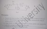
Transcribed Image Text:principle, calculate the ntal results.
R1
V3
R3 3.3
In
> I3
8.
V2
V1
I2
Fig. 5
Discussion
versity
1. Connect the circuit as in Fig. 5. Take V 10 V,
1KD, R2- 2.7 KO, R3- 3.3 KO, and
V2-8 V. With the help of equation (1)(in theory Section), calculate the node voltage V3,
branch currents I1, I2, and I3.
2. Using Circuit in Fig.
Verify
r results in previous question using superposition
your
Vs, I1, 12, and I3.
3. Compare the theoretical and
Expert Solution
This question has been solved!
Explore an expertly crafted, step-by-step solution for a thorough understanding of key concepts.
Step by stepSolved in 2 steps

Knowledge Booster
Learn more about
Need a deep-dive on the concept behind this application? Look no further. Learn more about this topic, electrical-engineering and related others by exploring similar questions and additional content below.Similar questions
- PARALLEL CIRCUIT 1. Create the circuit shown in figure B. Measure and record Vah, Vbg, Vcf, Vde, 16k, 13k and 12k and Itotal. 3. Compute the total resistance. 4. Using the formula Rt=Vah/It, compute for the total resistance. 5. Record the results in table 2. 2. a d V2 R6 S6kΩ R5 R4 –12V 3kn 2kn Figure B g f e Table 2 Vah Vbg Vcf Vde It 16k 13k 12k Rah Measured Values Computed Valuesarrow_forwardR3 R5 R1 A D 1k 2.2k 2.2k V1 V2 5Vdc R2 I, 4.7k R4 15Vdc 1k E H Figure1 The circuit shown Figure 1 will be used in this lab to study the Node Voltage and Mesh Current analysis techniques. The definition of each mesh current is given in the figure. For future convenience, the node voltage will be represented as 'Vx', where 'x' represents one node from a list of nodes such as 'A, B, C, D, E, F, G, H'. Write down two sets of symbolic equations leading to solve the circuit using Node voltage (1) and Mesh current methods. Explain which method is preferred to use for calculations.arrow_forwardR2 R3 ww 50 20 11 R4 20 R1 = 0 2A R6 30 V1 12V R5 120 V2 8V Solve the circuit to find: i. the current through R5 due to voltage source V1. ii. the current through R5 due to voltage source V2. iii. the current through R5 due to current source I1. iv. the total power loss in R5 due to all the three sources.arrow_forward
- For the given series parallel circuit shown in fig. 2 Find 11, 12, 13, 14, 15 V1,V2, V3,V4, & V5 R1 R3 50 20 R2 30 E1 -12 V LE3 -5V LE2 =12 V R5 R4 40 10arrow_forwardBased upon the following assumptions V1 = 28V R1 = 2.2kQ, R2 = 8380 R3 = 1.1k), R4 = 2 5k) R5 = 3.9k) If there is a load resistor = 680Q between A and B, use Thevenin's theorem and find the power dissipated in RTH with Rj in place State your answer in mW with 3 significant digits and only enter the number, no units. If necessary use scientific notation in the form 1200 = 1.2e3 or 0 012 = 1.2e-2. Notice it is power in RTH not Ri that we're looking for.arrow_forwardPlease show the solution by drawing the question in PSPICE orCAD environment.arrow_forward
- solve clear and correct or dislike Solve all parts or dislike a) How Many Branches Are in the Circuit?b) How Many Essentials Branches Are In The Circuit?c) How Many Nodes Are In the Circuit?d) How Mnay Essential Nodes Are In The Circuit?e) How Many Meshes Are In The Circuit?arrow_forward3. Please give a detailed solution on how it is solve.. Please give it step by step.. sorry for the inconvenience because I am still new at this.. thank youarrow_forwardSolve for the node voltages shown in the figure below. The component values are R₁ = 12, R₂ = 16, R3 = 12, R₁ = 7 and R5 = 7. (Figure 1) Figure R₂ www www R₂ M < 1 of 1 "O SP. OM EM, OPA R₁ Part A Determine the node voltage v₁. Part B Determine the node voltage v2.arrow_forward
- The primary voltage (v1) necessary to supply a 240V load (v2) is 1:15 V1 V2 RL Ideal Select one: a. 3600 V b. -16 V c. 16 V d. -3600 Varrow_forwardThe Quasstion in the pecturearrow_forwardExample: Find the current 1, in the network in Figure below. 6 k2 2V 12 k2 V2 V1 +, V3 12 k2 6 k2 V 6 V Solution:arrow_forward
arrow_back_ios
SEE MORE QUESTIONS
arrow_forward_ios
Recommended textbooks for you
 Introductory Circuit Analysis (13th Edition)Electrical EngineeringISBN:9780133923605Author:Robert L. BoylestadPublisher:PEARSON
 Delmar's Standard Textbook Of ElectricityElectrical EngineeringISBN:9781337900348Author:Stephen L. HermanPublisher:Cengage Learning
 Programmable Logic ControllersElectrical EngineeringISBN:9780073373843Author:Frank D. PetruzellaPublisher:McGraw-Hill Education
 Fundamentals of Electric CircuitsElectrical EngineeringISBN:9780078028229Author:Charles K Alexander, Matthew SadikuPublisher:McGraw-Hill Education
 Electric Circuits. (11th Edition)Electrical EngineeringISBN:9780134746968Author:James W. Nilsson, Susan RiedelPublisher:PEARSON
 Engineering ElectromagneticsElectrical EngineeringISBN:9780078028151Author:Hayt, William H. (william Hart), Jr, BUCK, John A.Publisher:Mcgraw-hill Education,

Introductory Circuit Analysis (13th Edition)
Electrical Engineering
ISBN:9780133923605
Author:Robert L. Boylestad
Publisher:PEARSON

Delmar's Standard Textbook Of Electricity
Electrical Engineering
ISBN:9781337900348
Author:Stephen L. Herman
Publisher:Cengage Learning

Programmable Logic Controllers
Electrical Engineering
ISBN:9780073373843
Author:Frank D. Petruzella
Publisher:McGraw-Hill Education

Fundamentals of Electric Circuits
Electrical Engineering
ISBN:9780078028229
Author:Charles K Alexander, Matthew Sadiku
Publisher:McGraw-Hill Education

Electric Circuits. (11th Edition)
Electrical Engineering
ISBN:9780134746968
Author:James W. Nilsson, Susan Riedel
Publisher:PEARSON

Engineering Electromagnetics
Electrical Engineering
ISBN:9780078028151
Author:Hayt, William H. (william Hart), Jr, BUCK, John A.
Publisher:Mcgraw-hill Education,