Introductory Circuit Analysis (13th Edition)
13th Edition
ISBN: 9780133923605
Author: Robert L. Boylestad
Publisher: PEARSON
expand_more
expand_more
format_list_bulleted
Question
1.
a) Sketch the phasor diagram, using current as the reference phasor, for a load consisting of a resistor and capacitor in series.
b) Sketch the phasor diagram, using current as the reference phasor, for a load consisting of a resistor and inductor in series.

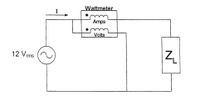
Transcribed Image Text:Wattmeter
Amps
Volts
12 Vrms
Expert Solution
This question has been solved!
Explore an expertly crafted, step-by-step solution for a thorough understanding of key concepts.
Step by stepSolved in 2 steps with 2 images

Knowledge Booster
Learn more about
Need a deep-dive on the concept behind this application? Look no further. Learn more about this topic, electrical-engineering and related others by exploring similar questions and additional content below.Similar questions
- Shown in the figure below is an "RL" circuit drive by an AC power source. The AC power source has an RMS voltage of Vps (RMS) = 9.84 Volts and is running at a frequency of f = 8.585e+04 Hz. The resistor has a resistance of R = 2170 and the inductor has an inductance of L = 3.54e-03 Henries. Vps R ww Write the FORMULA for the total impedance of the circuit Ztot = Determine the numerical value of Ztot = 2890.5 Determine the numerical value of $z= = 41 Determine the current through the circuit: • I(PEAK) = 4.81E-3 • I(RMS) = 3.404E-3 Determine the voltage across the resistor: • VR(PEAK) = 7.387 • VR(RMS) = 5.22 ✔✔ Amps ✔Amps Write the FORMULA for the phase of the total impedance of the circuit z... = | tan-1 2701 R x Volts X Volts Determine the voltage across the inductor: • VL(PEAK) = 9.184 • VL(RMS) = 6.49 ✔ Volts Volts L R²+ WL- ✔ degrees 2 If a second circuit were connected in parallel with the inductor, this circuit would be considered as: O a low-pass filter O a capacitive switcher…arrow_forwardGive a description of capacitive reactance and back up your description with examples/evidence.arrow_forwardAn electrical circuit with a sinusoidal voltage source, a resistor, and a capacitor all connected in series. The voltage across the capacitor: Select one: a. Leads the current in the capacitor by exactly 90o b. Is in phase with the sinusoidal voltage source c. Is in phase with the voltage across the resistor d. Leads the current in the circuit by 90o e. Lags the current in the circuit by 90oarrow_forward
- Assuming that a nonzero ac voltage source is applied, state whether the power and reactive power are positive, negative, or zero for a. a resistance in series with an inductance; b. a resistance in series with a capacitance. (Assume that the resistances, inductance, and capacitance are nonzero and finite in value.)arrow_forwardPlease show workarrow_forwardQ.4Determine the current flowing in the capacitor(-j25ohm) and its direction as shown in Figure below. Assume the voltage source to have negligible impedance.arrow_forward
- 3-10 A0.25-F capacitor has a current waveform i(t) as shown in Figure P3–10. Determine and plot the voltage waveform v(t) as a function of time. The capacitor is initially a and plot the voltage waveform v(t) as a function of time. The capacitor is imu uncharged. FIGURE P3-10 ilt) 4 A 6. -4 Aarrow_forwardConsider an ac power circuit containing an ideal inductor. Determine the phase shift between the waveforms of the inductor voltage and current. Consider the inductor voltage as the reference. How does the resistance of the wire coil in an actual inductor affect the phase shift between the inductor voltage and current?arrow_forwardfor a resistance and capicitance in a series with a voltage source, show that it is possible to draw a phasor diagram for the current and all voltages from magnitude measurment of these quantities only .illustrate your answer graphicallyarrow_forward
arrow_back_ios
SEE MORE QUESTIONS
arrow_forward_ios
Recommended textbooks for you
 Introductory Circuit Analysis (13th Edition)Electrical EngineeringISBN:9780133923605Author:Robert L. BoylestadPublisher:PEARSON
 Delmar's Standard Textbook Of ElectricityElectrical EngineeringISBN:9781337900348Author:Stephen L. HermanPublisher:Cengage Learning
 Programmable Logic ControllersElectrical EngineeringISBN:9780073373843Author:Frank D. PetruzellaPublisher:McGraw-Hill Education
 Fundamentals of Electric CircuitsElectrical EngineeringISBN:9780078028229Author:Charles K Alexander, Matthew SadikuPublisher:McGraw-Hill Education
 Electric Circuits. (11th Edition)Electrical EngineeringISBN:9780134746968Author:James W. Nilsson, Susan RiedelPublisher:PEARSON
 Engineering ElectromagneticsElectrical EngineeringISBN:9780078028151Author:Hayt, William H. (william Hart), Jr, BUCK, John A.Publisher:Mcgraw-hill Education,

Introductory Circuit Analysis (13th Edition)
Electrical Engineering
ISBN:9780133923605
Author:Robert L. Boylestad
Publisher:PEARSON

Delmar's Standard Textbook Of Electricity
Electrical Engineering
ISBN:9781337900348
Author:Stephen L. Herman
Publisher:Cengage Learning

Programmable Logic Controllers
Electrical Engineering
ISBN:9780073373843
Author:Frank D. Petruzella
Publisher:McGraw-Hill Education

Fundamentals of Electric Circuits
Electrical Engineering
ISBN:9780078028229
Author:Charles K Alexander, Matthew Sadiku
Publisher:McGraw-Hill Education

Electric Circuits. (11th Edition)
Electrical Engineering
ISBN:9780134746968
Author:James W. Nilsson, Susan Riedel
Publisher:PEARSON

Engineering Electromagnetics
Electrical Engineering
ISBN:9780078028151
Author:Hayt, William H. (william Hart), Jr, BUCK, John A.
Publisher:Mcgraw-hill Education,