Introductory Circuit Analysis (13th Edition)
13th Edition
ISBN: 9780133923605
Author: Robert L. Boylestad
Publisher: PEARSON
expand_more
expand_more
format_list_bulleted
Concept explainers
Question

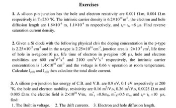
Transcribed Image Text:Exercises
1. A silicon p-n junction has the hole and electron resistivity are 0.001 .m, 0.004 .m
respectively in T-250 °K. The intrinsic carrier density is 6.2×10¹0 m³, the electron and hole
diffusion length are 1.8×10⁴ m, 1.1×10⁴ m respectively, and th=8 µs. Find reverse
saturation current density.
2. Given a Si diode with the following physical ch/s the doping concentration in the p-type
is 2.25×10¹7 cm³ and in the n-type is 2.25×10¹4 cm³, junction area is 2×10³ cm², life time
of hole in n-region=10 µs, life time of electron in p-region =50 µs, hole and electron
mobilities are 600 cm³V's¹ and 2100 cm²V¹s¹ respectively, the intrinsic carrier
concentration is 1.4x100 cm³ and the voltage is 0.66 v operation at room temperature.
Calculate Jp(0) and Jn(0) then calculate the total diode current.
3. A silicon p-n junction has energy of C.B. and V.B. are 0.9 eV, 0.1 eV respectively at 200
K. the hole and electron mobility, resistivity are 0.16 m²/V.s, 0.36 m²/V.s, 0.0025 92.m and
0.005 2.m. the electric field is 2x1028 V/m, me =0.8mo, m'h=0.5 mo, and t= th=10 μs,
find:
1. The Built in voltage. 2. The drift currents. 3. Electron and hole diffusion length.
Expert Solution
This question has been solved!
Explore an expertly crafted, step-by-step solution for a thorough understanding of key concepts.
This is a popular solution
Trending nowThis is a popular solution!
Step by stepSolved in 4 steps with 3 images

Knowledge Booster
Learn more about
Need a deep-dive on the concept behind this application? Look no further. Learn more about this topic, electrical-engineering and related others by exploring similar questions and additional content below.Similar questions
- A. Why does the conductivity of a semiconductor and some insulators change with impurity content? Compare this with the behaviour of metallic conductors. B. Discuss the location of the Fermi levels of intrinsic and extrinsic (n-type and p-type) semiconductors in low temperature and high temperature ranges. C. Discuss why the structure of the p-n junction is so important to modern technologies that impact our daily life.arrow_forwardConsider an idealized diode with a reverse saturation current 0.01 mA and an abrupt turn-on voltage of 0.7 V (assume no breakdown and operation away from the knee of the diode curve). For the circuit shown, both resistors are 100 2, the constant source is Vp = 5 V, and the time-dependent source is V3 = 20 sin(at) V. Calculate (a) the peak positive voltage V and the associated current through the diode and (b) the peak negative voltage V and the associated current through the diode. Rulamting R Vs + > KHIarrow_forward2. Given a Si diode with the following physical ch/s the doping concentration in the p-type is 2.25x10" em" and in the n-type is 2.25x10"cm", junction area is 2x10° em', life time of hole in n-region-10 us, life time of electron in p-region -50 us, hole and electron mobility's are 600 em'v's' and 2100 cm'v's" respectively, the intrinsic carrier concentration is 1.4x10" cm und the voltage is 0.66 v operation at room temperature. Calculate Jo and Ju, then calculate the total diode current.arrow_forward
- I. SOLVE THE FOLLONING PROBLENS : A COPPER WIRE OF 0,3 Mm RAAUS HAS A LEN ETH OF 1. JOM- IF THE RESISTIVITY of cOpPER IS 1-7 x0 WHAT WOULD BE THE RESISTANOE OF THE WIRE? OF A 100m WIRE IS 1035 mm AND 3.7 OHMS. WHAT 2. THE DIAMETER THE REISTANCE IS IS THE CONDUCTIVITY 3. WHAT WILL BE THE VALUE OF A CAPACITOR WHEN IT HAS A CAPACITIVE REACTANCE OF 300R ANP to A 6o HZ. SUPPLY? IN FARADS IS CONNECTED 4. WHAT Is THE VALUE OF THE RESISTOR WITH THE FOLLOWING COLORS ? A. BROWN, BLACK, GOLD, REP B. BLUE YELON BROWN, SILVER PED, SILVER, BROWN, VIOET C. 5. AND t WHEN V 220V AND R= 50n WHEN I = 45 A WHEN V = 120V FIND V ANO R 80n AND AND E= 11A-arrow_forwardPlease Help ASAP!!! Just do A-Carrow_forwardsemiconductorsarrow_forward
- Please show all work, thank you :)arrow_forwardB5arrow_forward3. In the following circuits, given source voltage Vs=9V, R1, R2 and R3 all are 1kOhms. Answer the questions by considering the diodes as ideal and practical silicon ones respectively. Vs Vs Vs R2 R2 R2 Vout P D R1 R1 R3 R1 (a) Vout = ? (b) Vp = ? (c) Vp = ? Note: Vp means the voltage at point p. warrow_forward
arrow_back_ios
arrow_forward_ios
Recommended textbooks for you
 Introductory Circuit Analysis (13th Edition)Electrical EngineeringISBN:9780133923605Author:Robert L. BoylestadPublisher:PEARSON
 Delmar's Standard Textbook Of ElectricityElectrical EngineeringISBN:9781337900348Author:Stephen L. HermanPublisher:Cengage Learning
 Programmable Logic ControllersElectrical EngineeringISBN:9780073373843Author:Frank D. PetruzellaPublisher:McGraw-Hill Education
 Fundamentals of Electric CircuitsElectrical EngineeringISBN:9780078028229Author:Charles K Alexander, Matthew SadikuPublisher:McGraw-Hill Education
 Electric Circuits. (11th Edition)Electrical EngineeringISBN:9780134746968Author:James W. Nilsson, Susan RiedelPublisher:PEARSON
 Engineering ElectromagneticsElectrical EngineeringISBN:9780078028151Author:Hayt, William H. (william Hart), Jr, BUCK, John A.Publisher:Mcgraw-hill Education,

Introductory Circuit Analysis (13th Edition)
Electrical Engineering
ISBN:9780133923605
Author:Robert L. Boylestad
Publisher:PEARSON

Delmar's Standard Textbook Of Electricity
Electrical Engineering
ISBN:9781337900348
Author:Stephen L. Herman
Publisher:Cengage Learning

Programmable Logic Controllers
Electrical Engineering
ISBN:9780073373843
Author:Frank D. Petruzella
Publisher:McGraw-Hill Education

Fundamentals of Electric Circuits
Electrical Engineering
ISBN:9780078028229
Author:Charles K Alexander, Matthew Sadiku
Publisher:McGraw-Hill Education

Electric Circuits. (11th Edition)
Electrical Engineering
ISBN:9780134746968
Author:James W. Nilsson, Susan Riedel
Publisher:PEARSON

Engineering Electromagnetics
Electrical Engineering
ISBN:9780078028151
Author:Hayt, William H. (william Hart), Jr, BUCK, John A.
Publisher:Mcgraw-hill Education,