
Introductory Circuit Analysis (13th Edition)
13th Edition
ISBN: 9780133923605
Author: Robert L. Boylestad
Publisher: PEARSON
expand_more
expand_more
format_list_bulleted
Related questions
Question
number 1 only please thank you

Transcribed Image Text:The power output is
(75 x103) = (0.79)(75 x 10) W
326
And so
(0.79 )(75 x 103
Nmax =
= 97.53%
(0.79)(75 x 10')+750+750
138
Assessment Task 6
1. A quantity is expressed in per unit if it is divided by a chosen base quantity
having the same physical dimension). Suppose that for a 10-kVA,
2400-V/240-V transformer we choose
P_(base )=10kW v_[1 base )=2400v v_(2 base )=240V
This transformer has the following test data
open-circuit test (on low-voltage side):
short-circuit test (on high-voltage side):
Convert all test data into per-unit values and find the series equivalent
240 V, 0.8 A, 80 W
80 V, 5.1 A, 220 w
resistance in per unit.
2. The results of open-circuit and short-circuit tests on a 25-kVA, 440-V/220-V,
60-Hz transformer are as follows:
Open-circuit test. Primary open-circuited, with instrumentation on the low-
voltage side. Input voltage, 220 V; input current, 9.6 A; input power, 710 w.
Short-circuit test. Secondary short-circuited, with instrumentation on the high-
voltage side. Input voltage, 42 V; input current, 57 A; input power, 1030 W.
Obtain the parameters of the exact equivalent circuit (Figure. 2-4), referred to the
high voltage side. Assume that R, = a'R:
3. A 110-kVA, 2200-V/ 110-V, 60-Hz transformer has the following circuit constants:
R1= 0.22 0, R; = 0.5 mo, X, = 2.00, X2 = 5 m0, Rc = 5.5 ko, and Xm = 1.1 kn. During
and X1= a'X2 voltage side
one day (24 hours) the transformer has the following load cycle: 4 h on no-load;
8h on % full-load at 0.8 power factor; 8 h on 14 full-load at unity power factor; and
; and 4 h on full-load at unity power factor. Assuming a constant core loss of
1.346 kW. Find the all-day efficiency of the transformer
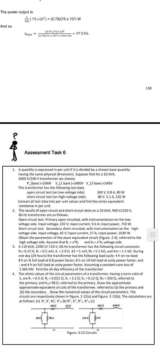
4. The ohmic values of the circuit parameters of a transformer, having a turns ratio of
5, are R: = 0.5 0; R2 = 0.021 0; X: = 3.2 0; X2 = 0.12 Q; Rc = 350 n, referred to
the primary; and Xm= 98 0, referred to the primary. Draw the approximate
approximate equivalent circuits of the transformer, referred to (a) the primary and
(b) the secondary.. Show the numerical values of the circuit parameters. The
circuits are respectively shown in Figure. 2-12(a) and Figure. 2-12(b). The calculations are
as follows: (a) R', X', Rc', X'm (b) R", X", R"c. X"m (c)
102s a
m
AR A
(a)
(b)
Figure. 6.12 Circuits
Expert Solution
This question has been solved!
Explore an expertly crafted, step-by-step solution for a thorough understanding of key concepts.

Step by stepSolved in 3 steps

Knowledge Booster


Learn more about
Need a deep-dive on the concept behind this application? Look no further. Learn more about this topic, electrical-engineering and related others by exploring similar questions and additional content below.Similar questions
- Please click on pic to open itarrow_forwardI don't understand how you got the kp value. Could you break it into more steps please?arrow_forwardConvert 214 ºF to engineering notation using the appropriate SI unit. (You must provide an answer before moving to the next part.) 214 ºF in SI unit using the proper engineering notation is written as K.arrow_forward
arrow_back_ios
arrow_forward_ios
Recommended textbooks for you
- Introductory Circuit Analysis (13th Edition)Electrical EngineeringISBN:9780133923605Author:Robert L. BoylestadPublisher:PEARSON
 Delmar's Standard Textbook Of ElectricityElectrical EngineeringISBN:9781337900348Author:Stephen L. HermanPublisher:Cengage Learning
 Programmable Logic ControllersElectrical EngineeringISBN:9780073373843Author:Frank D. PetruzellaPublisher:McGraw-Hill Education
  Fundamentals of Electric CircuitsElectrical EngineeringISBN:9780078028229Author:Charles K Alexander, Matthew SadikuPublisher:McGraw-Hill Education
 Electric Circuits. (11th Edition)Electrical EngineeringISBN:9780134746968Author:James W. Nilsson, Susan RiedelPublisher:PEARSON
 Engineering ElectromagneticsElectrical EngineeringISBN:9780078028151Author:Hayt, William H. (william Hart), Jr, BUCK, John A.Publisher:Mcgraw-hill Education,
Introductory Circuit Analysis (13th Edition)
Electrical Engineering
ISBN:9780133923605
Author:Robert L. Boylestad
Publisher:PEARSON
Delmar's Standard Textbook Of Electricity
Electrical Engineering
ISBN:9781337900348
Author:Stephen L. Herman
Publisher:Cengage Learning
Programmable Logic Controllers
Electrical Engineering
ISBN:9780073373843
Author:Frank D. Petruzella
Publisher:McGraw-Hill Education
Fundamentals of Electric Circuits
Electrical Engineering
ISBN:9780078028229
Author:Charles K Alexander, Matthew Sadiku
Publisher:McGraw-Hill Education
Electric Circuits. (11th Edition)
Electrical Engineering
ISBN:9780134746968
Author:James W. Nilsson, Susan Riedel
Publisher:PEARSON
Engineering Electromagnetics
Electrical Engineering
ISBN:9780078028151
Author:Hayt, William H. (william Hart), Jr, BUCK, John A.
Publisher:Mcgraw-hill Education,