Elements Of Electromagnetics
7th Edition
ISBN: 9780190698614
Author: Sadiku, Matthew N. O.
Publisher: Oxford University Press
expand_more
expand_more
format_list_bulleted
Question
thumb_up100%

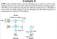
Transcribed Image Text:Example 8
1-55: In the structure shown, an 8 mm diameter pin is used at A, and 12-mm-
diameter pins are used at B and D. Knowing that the ultimate shearing stress is
100 MPa at all connections and that the ultimate normal stress is 250 MPa in
each of the two links joining B and D, determine the allowable load P if an
overall factor of safety of 3.0 is desired.
Top view
k200 mm 180 mm
12 mm
8 mm
B
C
B
A
B
20 mm
8 mm
8 mm
12 mm
Front view
Side view
Expert Solution
This question has been solved!
Explore an expertly crafted, step-by-step solution for a thorough understanding of key concepts.
This is a popular solution
Trending nowThis is a popular solution!
Step by stepSolved in 3 steps with 1 images

Knowledge Booster
Learn more about
Need a deep-dive on the concept behind this application? Look no further. Learn more about this topic, mechanical-engineering and related others by exploring similar questions and additional content below.Similar questions
- 4arrow_forwardTwo metal bars are fastened together at the bolted flange connection shown. There are 4 total bolts connecting the two metal bars together and each bolt has diameter = 50° with dbolt 12.7 mm. The flange is oriented at angle respect to longitudinal axis of the metal bars. If an axial force F = 40 kN is applied as shown, determine the overall safety factor of the bolted connection. You may assume the bolts are made out of 1020HR steel and the strength of the bolt in shear is 50% of the tensile strength of the bolt material. = F SFO overall = Ө number (rtol=0.01, atol=1e-05) F ?arrow_forwardRequired information A 920-mm (4) strip of steel (E= 200 GPa) is bent into a full circle by two couples applied as shown. NOTE: This is a multi-part question. Once an answer is submitted, you will be unable to return to this part. M' M mm Determine the maximum thickness t of the strip if the allowable stress of the steel is 420 MPa. The maximum thickness t of the strip is mm.arrow_forward
- - once answered correctly will UPVOTE!!arrow_forwardTwo metal bars are fastened together at the bolted flange connection shown. There are 2 total bolts connecting the two metal bars together and each bolt has diameter dbolt 12.7 mm. The flange is oriented at angle = 50° with respect to longitudinal axis of the metal bars. If an axial force F = 30 kN is applied as shown, determine the overall safety factor of the bolted connection. You may assume the bolts are made out of 1020HR steel and the strength of the bolt in shear is 50% of the tensile strength of the bolt material. F - SF overall = 0 number (rtol=0.01, at F ?arrow_forward4) The composite shaft consists of a solid brass segment (1) and a solid aluminum segment (2) that are connected at flange B and securely attached to rigid walls at A and C. Brass segment (1) has a diameter of 18 mm, a length of L₁ = 235 mm, and a shear modulus of 39 GPa. Aluminum segment (2) has a diameter of 24 mm, a length of L₂ = 165 mm, and a shear modulus of 28 GPa. If a concentrated torque of 270 Nm is applied to flange B, determine (a) the maximum shear stress magnitudes in segments (1) and (2). (b) the rotation angle of flange B relative to support A. N y A 235 mm (1) B 165 mm 270 N-m (2) C xarrow_forward
- number 11arrow_forwardPart A -80 mm- P 75 mm -40 mm 30 mm If the bolt head and the supporting bracket are made of the same material having a failure shear stress of Tfail = 150 MPa, determine the maximum allowable force P that can be applied to the bolt so that it does not pull through the support. Apply a factor of safety of F.S. = 2.5 against shear failure. Express your answer to three significant figures and include the appropriate units.arrow_forwardFBD 3. Determine the required thickness of member BC and the diameter of the pins at A and B if the failure normal stress for member BC is Ofail = 30 ksi, and the failure shear stress for the pins is Tfail = 12 ksi. Use a safety factor of 1.2 to your design. Solution: 1.5 in. 60° 8 ft 5 kip/ftarrow_forward
arrow_back_ios
arrow_forward_ios
Recommended textbooks for you
 Elements Of ElectromagneticsMechanical EngineeringISBN:9780190698614Author:Sadiku, Matthew N. O.Publisher:Oxford University Press
 Mechanics of Materials (10th Edition)Mechanical EngineeringISBN:9780134319650Author:Russell C. HibbelerPublisher:PEARSON
 Thermodynamics: An Engineering ApproachMechanical EngineeringISBN:9781259822674Author:Yunus A. Cengel Dr., Michael A. BolesPublisher:McGraw-Hill Education
 Control Systems EngineeringMechanical EngineeringISBN:9781118170519Author:Norman S. NisePublisher:WILEY
 Mechanics of Materials (MindTap Course List)Mechanical EngineeringISBN:9781337093347Author:Barry J. Goodno, James M. GerePublisher:Cengage Learning
 Engineering Mechanics: StaticsMechanical EngineeringISBN:9781118807330Author:James L. Meriam, L. G. Kraige, J. N. BoltonPublisher:WILEY

Elements Of Electromagnetics
Mechanical Engineering
ISBN:9780190698614
Author:Sadiku, Matthew N. O.
Publisher:Oxford University Press

Mechanics of Materials (10th Edition)
Mechanical Engineering
ISBN:9780134319650
Author:Russell C. Hibbeler
Publisher:PEARSON

Thermodynamics: An Engineering Approach
Mechanical Engineering
ISBN:9781259822674
Author:Yunus A. Cengel Dr., Michael A. Boles
Publisher:McGraw-Hill Education

Control Systems Engineering
Mechanical Engineering
ISBN:9781118170519
Author:Norman S. Nise
Publisher:WILEY

Mechanics of Materials (MindTap Course List)
Mechanical Engineering
ISBN:9781337093347
Author:Barry J. Goodno, James M. Gere
Publisher:Cengage Learning

Engineering Mechanics: Statics
Mechanical Engineering
ISBN:9781118807330
Author:James L. Meriam, L. G. Kraige, J. N. Bolton
Publisher:WILEY