Elements Of Electromagnetics
7th Edition
ISBN: 9780190698614
Author: Sadiku, Matthew N. O.
Publisher: Oxford University Press
expand_more
expand_more
format_list_bulleted
Concept explainers
Question
Please don't Hold as fast as.

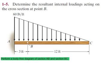
Transcribed Image Text:1-5. Determine the resultant internal loadings acting on
the cross section at point B.
60 lb/ft
A
B
- 3 ft
Perform a body-free diagram of section AB and section BC.
12 ft
C
Expert Solution
This question has been solved!
Explore an expertly crafted, step-by-step solution for a thorough understanding of key concepts.
This is a popular solution
Trending nowThis is a popular solution!
Step by stepSolved in 2 steps with 2 images

Knowledge Booster
Learn more about
Need a deep-dive on the concept behind this application? Look no further. Learn more about this topic, mechanical-engineering and related others by exploring similar questions and additional content below.Similar questions
- Adjustable Link L m Pivot Pivot Screw 'B' Gripper In the drawing, arm A is being driven back and forth in the direction of the arrows. It is connected to a gripper by way of an adjustable link L, two horizontal bars and two vertical bars. Screw B is a shoulder screw secured to arm A, but allows the horizontal bar to pivot around it. If the shoulder screw B was lowered towards the end of arm A, and the stroke of arm A remained the same, the stroke of the gripper would: Arm 'A' 0 MIMINIAarrow_forwardDon't give handwritten otherwise i will downvotearrow_forwardFor nos. 21-23, satisfy the conditions of the given problem below: As an airplane's brakes are applied, the nose wheel exerts two forces on the end of the landing gear as shown in the figure 1. Determine: 21. the force in the strut AB. * 1 point 30° 450 lb. 1350 lb O A. 215.3 lb B. 224.4 lb C. 233. 2 lb D. 234.3 lb 1 ft 2 ftarrow_forward
- Two blocks A and B, each having a mass of 5.5 kg , are connected by pins using the linkages shown. A В 0, 02 The coefficient of static friction between Block A and the floor is u A= 0.21. The coefficient of static friction between Block B and the floor is µB= 0.44. The angles given are 01 = 45 degrees 02 = 28 degrees Neglect the weight of the links. i. Draw the Free Body Diagrams for pin C, Block A, and Block B. ii. Applied force P on pin C is gradually raised. Which block starts slipping first and what is the value of P when slippage starts occurring? Hint: It helps to establish two cases, one in which block A slips and one in which block B slips, and then calculate what occurs in each case in order to determine what happens. Part A - Part A Draw the Free Body Diagram for link C. Note that for this problem we are looking at the starting location of the vectors. Draw the vectors starting at the gold dot at point C. The location of the starting point as well as the orientation of your…arrow_forwardSketch a pulley system that will give a 2 to 1 mechanical advantage. Provide a free body diagram illustrating the key forces involved.arrow_forward5. For the engine-transmission-propeller problem shown below, The engine generates a torque of 219lb-ft, and it is bolted to a frame at locations A and B. The transmission reverses the rotation direction. The transmission ratio is 1.5 (i.e. the propeller speed is -1/1.5 the engine speed, the minus sign indicates the change in direction). d. Sketch the free body diagram. Be sure to show the torques at the input and outputs to the different components. Note the change in the rotation direction between the engine and shaft. e. Solve for the reaction forces at the bolt supports of the engine, if the distance between them is 1 ft. Propeller Engine Reduction ratio 1.5 Engine is attached Barrow_forward
- 5. There is a small amount of friction in the bearings of the pulley wheel. Suggest a way to measure this friction force (in grams).arrow_forwardA 1" diameter line shaft, which is supported by frictionless pulleys at the ends, carries 2 pulleys. The 10" diameter driver pulley is driven in a counter-clockwise direction, and its belt tensions are 25 lbs and 56 lbs. The 2" diameter driven pulley has one of its belt tensions measured at 30 lbs. Calculate the missing belt tension.arrow_forward
arrow_back_ios
arrow_forward_ios
Recommended textbooks for you
 Elements Of ElectromagneticsMechanical EngineeringISBN:9780190698614Author:Sadiku, Matthew N. O.Publisher:Oxford University Press
 Mechanics of Materials (10th Edition)Mechanical EngineeringISBN:9780134319650Author:Russell C. HibbelerPublisher:PEARSON
 Thermodynamics: An Engineering ApproachMechanical EngineeringISBN:9781259822674Author:Yunus A. Cengel Dr., Michael A. BolesPublisher:McGraw-Hill Education
 Control Systems EngineeringMechanical EngineeringISBN:9781118170519Author:Norman S. NisePublisher:WILEY
 Mechanics of Materials (MindTap Course List)Mechanical EngineeringISBN:9781337093347Author:Barry J. Goodno, James M. GerePublisher:Cengage Learning
 Engineering Mechanics: StaticsMechanical EngineeringISBN:9781118807330Author:James L. Meriam, L. G. Kraige, J. N. BoltonPublisher:WILEY

Elements Of Electromagnetics
Mechanical Engineering
ISBN:9780190698614
Author:Sadiku, Matthew N. O.
Publisher:Oxford University Press

Mechanics of Materials (10th Edition)
Mechanical Engineering
ISBN:9780134319650
Author:Russell C. Hibbeler
Publisher:PEARSON

Thermodynamics: An Engineering Approach
Mechanical Engineering
ISBN:9781259822674
Author:Yunus A. Cengel Dr., Michael A. Boles
Publisher:McGraw-Hill Education

Control Systems Engineering
Mechanical Engineering
ISBN:9781118170519
Author:Norman S. Nise
Publisher:WILEY

Mechanics of Materials (MindTap Course List)
Mechanical Engineering
ISBN:9781337093347
Author:Barry J. Goodno, James M. Gere
Publisher:Cengage Learning

Engineering Mechanics: Statics
Mechanical Engineering
ISBN:9781118807330
Author:James L. Meriam, L. G. Kraige, J. N. Bolton
Publisher:WILEY