
Elements Of Electromagnetics
7th Edition
ISBN: 9780190698614
Author: Sadiku, Matthew N. O.
Publisher: Oxford University Press
expand_more
expand_more
format_list_bulleted
Related questions
Concept explainers
Question
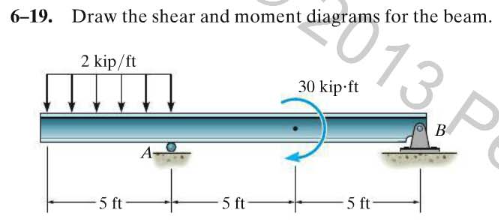
Derive the equations for shear force and bending moment

Transcribed Image Text:013P
6-19. Draw the shear and moment diagrams for the beam.
2 kip/ft
30 kip-ft
3.F
A
5 ft
5 ft
5 ft
Expert Solution
This question has been solved!
Explore an expertly crafted, step-by-step solution for a thorough understanding of key concepts.

This is a popular solution

Trending nowThis is a popular solution!

Step by stepSolved in 3 steps with 3 images

Knowledge Booster


Learn more about
Need a deep-dive on the concept behind this application? Look no further. Learn more about this topic, mechanical-engineering and related others by exploring similar questions and additional content below.Similar questions
- Part (b)arrow_forwardActivity 3 A rig is to be constructed, which will consist of a 10m long elastic beam, simply supported at both ends, as shown in Figure 1. The first simply supported beam is subjected to the concentrated loads and the second beam is subjected to the distribution and point loads. Determine the distribution of shear force. Calculate the bending moments, due to bending in the simply supported beam. 500N 1000N 2000N 500N 2m Im lm lm Im 4m Figure 3: SSB with point loads 80 UDL: 10 (KNm) 2 (m) 7 (m) Figure 4: SSB with the combination of point and distribution loadarrow_forward6. Finds the bending stress and equivalent bending load due to bending of a 6 x 19 (Fiber core) wire rope of ½ in. diameter around a 24 in. pitch diameter sheave.arrow_forward
- Define the term bending stress?arrow_forwardFor the figure below, draw free-body diagrams for both the vertical and horizontal portions of the structure supporting the pulley and determine all reaction forces and moments. Then determine the shear and bending moment diagrams for both portions of the structure. Assume the mass of the structure and pulley are negligible. 48 in. 12 in. Cable 100 lb 12 in. pulley rad. 27 in. Cable 100 lbarrow_forward5c and 5darrow_forward
- 3. Draw a schematic of the standard convention for the meaning of positive shears and bending moments (see Section 8.2). Use your diagram to help you answer 4 And 5. 4. Determine the internal shear at a section passing through point D. 5. Determine the internal bending moment at a section passing through point. The answers should be according to the answer key- 4. VD = 2000 lb (up) 5. MD = 1556 N-m (clockwise)arrow_forwardDescribe the Graphical method for constructing Shear and Moment Diagrams?arrow_forwardThe figure shows a round shaft from a gear transmission. Gears are mounted at points A, C, and E. Supporting bearings are at B and D. The forces transmitted from the gears to the shaft are shown, all acting downward. Compute the maximum stress due to bending in the shaft, accounting for stress concentrations. Draw shear diagram and moment diagram. calculate the safety factor for the material selected. The material is 4150 OQT 1300. Assume that f1 = 9.5 KN , f2= 13.5 KN and f3 =18 KNarrow_forward
- Can you provide me the step by step process of this? Thank you! Use the graphical method to construct the bending-moment diagram and identify the magnitude of the largest moment (consider both positive and negative). The ground reactions and shear-force diagram are provided.MA = 22 kN-mMB = 10 kN-mAy = 17.00 kNBy = 13.00 kNarrow_forwardSketch the graphs of the shear and bending - moment equations for the following situations, where the beam length is L and the point load force is P. Carrow_forward1. Estimate the endurance strength of a 1.5-in-diameter rod of AISI 1040 steel having a machine finish and heat-treated to a tensile strength of 110kpsi, loaded in rotating bending.arrow_forward
arrow_back_ios
SEE MORE QUESTIONS
arrow_forward_ios
Recommended textbooks for you
- Elements Of ElectromagneticsMechanical EngineeringISBN:9780190698614Author:Sadiku, Matthew N. O.Publisher:Oxford University Press
 Mechanics of Materials (10th Edition)Mechanical EngineeringISBN:9780134319650Author:Russell C. HibbelerPublisher:PEARSON
 Thermodynamics: An Engineering ApproachMechanical EngineeringISBN:9781259822674Author:Yunus A. Cengel Dr., Michael A. BolesPublisher:McGraw-Hill Education
  Control Systems EngineeringMechanical EngineeringISBN:9781118170519Author:Norman S. NisePublisher:WILEY
 Mechanics of Materials (MindTap Course List)Mechanical EngineeringISBN:9781337093347Author:Barry J. Goodno, James M. GerePublisher:Cengage Learning
 Engineering Mechanics: StaticsMechanical EngineeringISBN:9781118807330Author:James L. Meriam, L. G. Kraige, J. N. BoltonPublisher:WILEY
Elements Of Electromagnetics
Mechanical Engineering
ISBN:9780190698614
Author:Sadiku, Matthew N. O.
Publisher:Oxford University Press
Mechanics of Materials (10th Edition)
Mechanical Engineering
ISBN:9780134319650
Author:Russell C. Hibbeler
Publisher:PEARSON
Thermodynamics: An Engineering Approach
Mechanical Engineering
ISBN:9781259822674
Author:Yunus A. Cengel Dr., Michael A. Boles
Publisher:McGraw-Hill Education
Control Systems Engineering
Mechanical Engineering
ISBN:9781118170519
Author:Norman S. Nise
Publisher:WILEY
Mechanics of Materials (MindTap Course List)
Mechanical Engineering
ISBN:9781337093347
Author:Barry J. Goodno, James M. Gere
Publisher:Cengage Learning
Engineering Mechanics: Statics
Mechanical Engineering
ISBN:9781118807330
Author:James L. Meriam, L. G. Kraige, J. N. Bolton
Publisher:WILEY