Introductory Circuit Analysis (13th Edition)
13th Edition
ISBN: 9780133923605
Author: Robert L. Boylestad
Publisher: PEARSON
expand_more
expand_more
format_list_bulleted
Concept explainers
Question
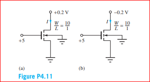
Identify the source, drain, gate, and bulk terminals
and find the current I in the transistors
Assume VTN = 0.70 V

Transcribed Image Text:+0.2 V
-0.2 V
W_ 10
W 10
+5
+5
(a)
(b)
Figure P4.11
Expert Solution
This question has been solved!
Explore an expertly crafted, step-by-step solution for a thorough understanding of key concepts.
This is a popular solution
Trending nowThis is a popular solution!
Step by stepSolved in 2 steps with 2 images

Knowledge Booster
Learn more about
Need a deep-dive on the concept behind this application? Look no further. Learn more about this topic, electrical-engineering and related others by exploring similar questions and additional content below.Similar questions
- Consider an nMOS with tox=9 nm, µn=500cm²/Vs, Vt=0.7V, and W/L=10. Find the drain currents for the following cases: i. Ves=5 and VDs=5V ii. Ves=5 V and VDs=1Varrow_forwardList the three distinct operation regions of a MOSFET and identify the region providing the highest gain. L2 Pg 2 produce a drain current of 10 mà from anarrow_forwardDetermine vo versus v₁ for the circuit shown in Figure 2. Assume that the MOSFET operates in saturation and is characterized by the parameters K and VT. Vs R₁ www Figure 2 wwww RL R₂ wwwww VO Note: assuming the MOSFET works at normal saturation regime and ips= (VDS -VT)²2 K 2arrow_forward
- 2. Determine the VCB (i.e., voltage difference between collector C and base B) in the transistor circuit shown in the figure below. The transistor is silicon type (i.e., VBE is 0.7V) and has current gain hEE- 150. (Assume the transistor is working on active region) Rc 100 2 RB 10V Vcc 10 k2 VBR = 5Varrow_forwardA silicon controlled rectifier (SCR) has a forward breakdown voltage of 230 V. When a gate current of 2 mA flows in the gate circuit. If a sinusoidal voltage of 400 V peak is applied, find the following: Firing angle. Average output voltage. Average current for a load resistance of 180 Ohms. Power outputarrow_forward
arrow_back_ios
arrow_forward_ios
Recommended textbooks for you
 Introductory Circuit Analysis (13th Edition)Electrical EngineeringISBN:9780133923605Author:Robert L. BoylestadPublisher:PEARSON
 Delmar's Standard Textbook Of ElectricityElectrical EngineeringISBN:9781337900348Author:Stephen L. HermanPublisher:Cengage Learning
 Programmable Logic ControllersElectrical EngineeringISBN:9780073373843Author:Frank D. PetruzellaPublisher:McGraw-Hill Education
 Fundamentals of Electric CircuitsElectrical EngineeringISBN:9780078028229Author:Charles K Alexander, Matthew SadikuPublisher:McGraw-Hill Education
 Electric Circuits. (11th Edition)Electrical EngineeringISBN:9780134746968Author:James W. Nilsson, Susan RiedelPublisher:PEARSON
 Engineering ElectromagneticsElectrical EngineeringISBN:9780078028151Author:Hayt, William H. (william Hart), Jr, BUCK, John A.Publisher:Mcgraw-hill Education,

Introductory Circuit Analysis (13th Edition)
Electrical Engineering
ISBN:9780133923605
Author:Robert L. Boylestad
Publisher:PEARSON

Delmar's Standard Textbook Of Electricity
Electrical Engineering
ISBN:9781337900348
Author:Stephen L. Herman
Publisher:Cengage Learning

Programmable Logic Controllers
Electrical Engineering
ISBN:9780073373843
Author:Frank D. Petruzella
Publisher:McGraw-Hill Education

Fundamentals of Electric Circuits
Electrical Engineering
ISBN:9780078028229
Author:Charles K Alexander, Matthew Sadiku
Publisher:McGraw-Hill Education

Electric Circuits. (11th Edition)
Electrical Engineering
ISBN:9780134746968
Author:James W. Nilsson, Susan Riedel
Publisher:PEARSON

Engineering Electromagnetics
Electrical Engineering
ISBN:9780078028151
Author:Hayt, William H. (william Hart), Jr, BUCK, John A.
Publisher:Mcgraw-hill Education,