
Introductory Circuit Analysis (13th Edition)
13th Edition
ISBN: 9780133923605
Author: Robert L. Boylestad
Publisher: PEARSON
expand_more
expand_more
format_list_bulleted
Related questions
Question
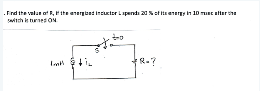

Transcribed Image Text:. Find the value of R, if the energized inductor L spends 20 % of its energy in 10 msec after the
switch is turned ON.
to
ImH
R=?
Expert Solution
This question has been solved!
Explore an expertly crafted, step-by-step solution for a thorough understanding of key concepts.

Step by stepSolved in 2 steps with 1 images

Knowledge Booster


Learn more about
Need a deep-dive on the concept behind this application? Look no further. Learn more about this topic, electrical-engineering and related others by exploring similar questions and additional content below.Similar questions
- A capacitor has a reactance of 40 when operated on a 50 Hz supply. Determine the value of its capacitance. In a series R–L circuit the p.d. across the resistance R is 12V and the p.d. across the inductance L is 5V. Find the supply voltage and the phase angle between current and voltagearrow_forward1. Capacitorsarrow_forwardDetermine the state of the diode D1. Use Vp - .7V 5.n FUE-SU 7° √₂= youarrow_forward
- The figure displays two circuits with a charged capacitor that is to be discharged through a resistor when a switch is closed. In figure (a) below, R₁ = 23.32 and C₁ = 5.04 μF. In figure (b) below, R2 = 10.82 and C₂ = 8.10 μF. The ratio of the initial charges on the two capacitors is 902/901 = 1.61. At time t = 0, both switches are closed. At what time t do the two capacitors have the same charge? 0.0 (a) (b) Number i Unitsarrow_forward1) Propose and draw a circuit of a resistive current divider in halfarrow_forwardPlease answer in typing format solution Sir please help Thanks in advancearrow_forward
- In the diagram below, the switch S has been closed for a long time. A) What is the output voltage Vout? What is the charge on the capacitor? b) The switch is opened, so the output voltage increases. What is the time constant that describes the charging of the capacitor in terms of R and C? c) When Vout reaches 10 V, the switch closes and the capacitor begins to discharge. What is the time constant that describes the discharging in terms of R and C? Hint: Apply Kirchhoff's Rules to both loops and the sum of the currents at the junction above the capacitor in the diagram, and use I=dq/dt. If the switch opens when Vout reaches a lower value, say 5V, the capacitor will charge again, and thus one can cycle the voltage with a time constant determined by the circuit: this demonstrates the principle of operation of an electronic timer. 4R S 15 V Vout Rarrow_forwardFind the Equivalent Capacitance between P and Q from the figure belowarrow_forwardExplain the inductor equation and what is going on?arrow_forward
arrow_back_ios
SEE MORE QUESTIONS
arrow_forward_ios
Recommended textbooks for you
- Introductory Circuit Analysis (13th Edition)Electrical EngineeringISBN:9780133923605Author:Robert L. BoylestadPublisher:PEARSON
 Delmar's Standard Textbook Of ElectricityElectrical EngineeringISBN:9781337900348Author:Stephen L. HermanPublisher:Cengage Learning
 Programmable Logic ControllersElectrical EngineeringISBN:9780073373843Author:Frank D. PetruzellaPublisher:McGraw-Hill Education
  Fundamentals of Electric CircuitsElectrical EngineeringISBN:9780078028229Author:Charles K Alexander, Matthew SadikuPublisher:McGraw-Hill Education
 Electric Circuits. (11th Edition)Electrical EngineeringISBN:9780134746968Author:James W. Nilsson, Susan RiedelPublisher:PEARSON
 Engineering ElectromagneticsElectrical EngineeringISBN:9780078028151Author:Hayt, William H. (william Hart), Jr, BUCK, John A.Publisher:Mcgraw-hill Education,
Introductory Circuit Analysis (13th Edition)
Electrical Engineering
ISBN:9780133923605
Author:Robert L. Boylestad
Publisher:PEARSON
Delmar's Standard Textbook Of Electricity
Electrical Engineering
ISBN:9781337900348
Author:Stephen L. Herman
Publisher:Cengage Learning
Programmable Logic Controllers
Electrical Engineering
ISBN:9780073373843
Author:Frank D. Petruzella
Publisher:McGraw-Hill Education
Fundamentals of Electric Circuits
Electrical Engineering
ISBN:9780078028229
Author:Charles K Alexander, Matthew Sadiku
Publisher:McGraw-Hill Education
Electric Circuits. (11th Edition)
Electrical Engineering
ISBN:9780134746968
Author:James W. Nilsson, Susan Riedel
Publisher:PEARSON
Engineering Electromagnetics
Electrical Engineering
ISBN:9780078028151
Author:Hayt, William H. (william Hart), Jr, BUCK, John A.
Publisher:Mcgraw-hill Education,