
Electronics Fundamentals: Circuits, Devices & Applications
8th Edition
ISBN: 9780135072950
Author: Thomas L. Floyd, David Buchla
Publisher: Prentice Hall
expand_more
expand_more
format_list_bulleted
Videos
Textbook Question
Chapter 12, Problem 1TFQ
In an ac circuit where
Expert Solution & Answer
To determine
To find: Whether in an ac circuit for the given condition is
Explanation of Solution
Given:
For an ac circuit, where
The phase angle is
Calculation:
Drawing the general ac circuit diagram for the series RL circuit:
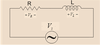
From the above diagram, the total impedance of the circuit is given as:
The phase angle for the circuit is given as:
Hence, the given result is correct.
Want to see more full solutions like this?
Subscribe now to access step-by-step solutions to millions of textbook problems written by subject matter experts!
Students have asked these similar questions
What is the voltage across the resistor for an AC series RC circuit with the following specs:
Source Voltsge = 13 V
Capacitor Voltage = 5 V
What will be magnitude of the total circuit impedance of a series LR circuit excited by a 100 Hz ac source? The resistance is 40 ohm and the inductance is 4 mF.
For an inductor in a sine-wave ac circuit,
VL lags iL by 90
VL and iL are in phase
VL leads iL by 90
Chapter 12 Solutions
Electronics Fundamentals: Circuits, Devices & Applications
Ch. 12 - In an ac circuit where R=XL, the phase angle is...Ch. 12 - Prob. 2TFQCh. 12 - In an ac series RL circuit, the current and...Ch. 12 - In an ac parallel RL circuit, the inductive...Ch. 12 - In an ac parallel RL circuit, the voltage across...Ch. 12 - The unit siemens is used to measure both...Ch. 12 - Prob. 7TFQCh. 12 - If the power factor of a circuit is 0.5, the...Ch. 12 - Prob. 9TFQCh. 12 - Prob. 10TFQ
Ch. 12 - In a series RL circuit, the resistor voltage Leads...Ch. 12 - Prob. 2STCh. 12 - Prob. 3STCh. 12 - If the frequency is doubled and the resistance is...Ch. 12 - Prob. 5STCh. 12 - Prob. 6STCh. 12 - Prob. 7STCh. 12 - Prob. 8STCh. 12 - Prob. 9STCh. 12 - Prob. 10STCh. 12 - Prob. 11STCh. 12 - Prob. 12STCh. 12 - If a load is purely inductive and the reactive...Ch. 12 - Prob. 14STCh. 12 - Prob. 15STCh. 12 - Determine the cause for each set of symptoms....Ch. 12 - Determine the cause for each set of symptoms....Ch. 12 - Prob. 3TSCCh. 12 - Prob. 4TSCCh. 12 - Prob. 5TSCCh. 12 - Prob. 1PCh. 12 - Prob. 2PCh. 12 - Find the impedance of each circuit in Figure...Ch. 12 - Determine the impedance and phase angle in each...Ch. 12 - In Figure 12-52, determine the impedance at each...Ch. 12 - Determine the values of R and XL in a series RL...Ch. 12 - If the frequency of the source is increased to 1...Ch. 12 - Determine the voltage across the total resistance...Ch. 12 - Find the current for each circuit of Figure 12-50.Ch. 12 - Calculate the total current in each circuit of...Ch. 12 - Determine for the cicutit in Figure 12-53.Ch. 12 - If the inductance in Figure 12-53 is doubled, does...Ch. 12 - Draw the waveforms for Vs,VRandVL in Figure 12-53....Ch. 12 - For the circuit in Figure 12-54, find VRandVL for...Ch. 12 - For the lag circuit in Figure 12-55, determine the...Ch. 12 - Repeat Problem 15 for the lead circuit in Figure...Ch. 12 - What is the impedance for the circuit in Figure...Ch. 12 - Repeat Problem 17 for the following frequencies:...Ch. 12 - At what frequecy does XL equal R in Figure 12-57?Ch. 12 - Find the total current and each branch current in...Ch. 12 - Determine the following quantities in Figure...Ch. 12 - Convert the circuit in Figure 12-60 to an...Ch. 12 - Determine the voltage across each element in...Ch. 12 - Is the circuit in Figure 12-61 predominantly...Ch. 12 - Find the current in each branch and the total...Ch. 12 - In a certain RL circuit, the true power is 100 mW,...Ch. 12 - Determine the true power and the reactive power in...Ch. 12 - What is the power factor in Figure 12-58?Ch. 12 - Determine Ptrue,Pr,Pa, and PF for the circuit in...Ch. 12 - Plot the response curve for the circuit in Figure...Ch. 12 - Using the same procedure as in Problem 30, plot...Ch. 12 - Draw the voltage phasor diagram for each circuit...Ch. 12 - Prob. 33PCh. 12 - Prob. 34PCh. 12 - Determine the voltage across the inductors in...Ch. 12 - Is the circuit in Figure 12-64 predominantly...Ch. 12 - Find the total current in Figure 12-64.Ch. 12 - Determine the phase shift and attenuation...Ch. 12 - Design an ideal inductive switching circuit that...Ch. 12 - Prob. 44PCh. 12 - Prob. 45PCh. 12 - Prob. 46PCh. 12 - Prob. 47PCh. 12 - Open file P12-48. Determine if there is a fault...Ch. 12 - Prob. 49P
Knowledge Booster


Learn more about
Need a deep-dive on the concept behind this application? Look no further. Learn more about this topic, electrical-engineering and related others by exploring similar questions and additional content below.Similar questions
- 3. An RLC series circuit has a resistor with a power consumption of 124 watts. The induc- tor has a reactive power of 366 VARST, and the capacitor has a reactive power of 288 VARSC. What is the circuit power factor?arrow_forwardIn an RL series circuit the frequency is 60Hz, the voltage above the resistor is 60, the inductance is 0.4 H and the angle is 30º. Calculate A) Inductive reactance B) Voltage drop in the inductor C) Current D) The impedancearrow_forward0 -V For the following circuit, the vo waveform is C ..... T ЛЕ Correct O Wrong Oarrow_forward
- In a purely inductive circuit, the inductor voltage and inductor current are 90 degrees out of phase. Which of the following apply to a purely inductive circuit? voltage lags current by 90 degrees O current leads voltage by 90 degrees voltage leads current by 90 degrees O current lags voltage by 90 degreesarrow_forwardDetermine the value of the output voltage in the figure given below, where ZC=-70. Please report your answer so the magnitude is positive and all angles are in the range of negative 180 degrees to positive 180 degrees. с 4/90° A j4Q m 292 www 2221 → 2/0° A 292 + 12/0° Varrow_forwardDo the following convolution sinc(600t)*sinc(1000t)arrow_forward
- Q6. Calculate the total current in the circuit below if the circuit is powered by the sine wave voltage source of 150 Vm and frequency 60 Hz. Draw the current phasor diagram and determine if this circuit fulfils the criteria of resonance. Vm Sine 60 Hz C L1 0.7 H L2 0.5 H relee cele Figure Q6 C1 5.1 mF C2 0.12 mF R1 120 22 R2 330 Ωarrow_forward3) Pure Inductance in Series Frequency = 60HZ EL1 = E2 = E13 = %3D ET = 2kVarrow_forwardCalculate the total current in the circuit below if the circuit is powered by the sine wave voltage source of 150 Vm and frequency 60 Hz. Draw the current phasor diagram and determine if this circuit fulfils the criteria of resonance. Vm Sine 60 Hz LI 0.7 H L2 0.5 H rele rele Figure Q6 C1 5.1 mF C2 -0.12 mF R1 120 Ω R2 330 Ωarrow_forward
- 17 Determine the current 13. 6 -j8 6 -j8 12 100 L0° 2+ j14 Z2 O 6.324-26.57° A O 6.32426.57° A 6.32L-71.57° A O 6.32471.57° A +arrow_forwardRc 16ke For the circuit shown in Figure. If VeE =-14V -14v 18V RB Vec=18 V, VeE = 8 V, IB= 8MA , B= 100arrow_forwardP In RL series circuit, voltage across resistor is 6V and voltage across inductor is 8V. Power factor of the circuit isarrow_forward
arrow_back_ios
SEE MORE QUESTIONS
arrow_forward_ios
Recommended textbooks for you
 Introductory Circuit Analysis (13th Edition)Electrical EngineeringISBN:9780133923605Author:Robert L. BoylestadPublisher:PEARSON
 Delmar's Standard Textbook Of ElectricityElectrical EngineeringISBN:9781337900348Author:Stephen L. HermanPublisher:Cengage Learning
 Programmable Logic ControllersElectrical EngineeringISBN:9780073373843Author:Frank D. PetruzellaPublisher:McGraw-Hill Education
 Fundamentals of Electric CircuitsElectrical EngineeringISBN:9780078028229Author:Charles K Alexander, Matthew SadikuPublisher:McGraw-Hill Education
 Electric Circuits. (11th Edition)Electrical EngineeringISBN:9780134746968Author:James W. Nilsson, Susan RiedelPublisher:PEARSON
 Engineering ElectromagneticsElectrical EngineeringISBN:9780078028151Author:Hayt, William H. (william Hart), Jr, BUCK, John A.Publisher:Mcgraw-hill Education,
Introductory Circuit Analysis (13th Edition)
Electrical Engineering
ISBN:9780133923605
Author:Robert L. Boylestad
Publisher:PEARSON
Delmar's Standard Textbook Of Electricity
Electrical Engineering
ISBN:9781337900348
Author:Stephen L. Herman
Publisher:Cengage Learning
Programmable Logic Controllers
Electrical Engineering
ISBN:9780073373843
Author:Frank D. Petruzella
Publisher:McGraw-Hill Education
Fundamentals of Electric Circuits
Electrical Engineering
ISBN:9780078028229
Author:Charles K Alexander, Matthew Sadiku
Publisher:McGraw-Hill Education
Electric Circuits. (11th Edition)
Electrical Engineering
ISBN:9780134746968
Author:James W. Nilsson, Susan Riedel
Publisher:PEARSON
Engineering Electromagnetics
Electrical Engineering
ISBN:9780078028151
Author:Hayt, William H. (william Hart), Jr, BUCK, John A.
Publisher:Mcgraw-hill Education,
02 - Sinusoidal AC Voltage Sources in Circuits, Part 1; Author: Math and Science;https://www.youtube.com/watch?v=8zMiIHVMfaw;License: Standard Youtube License