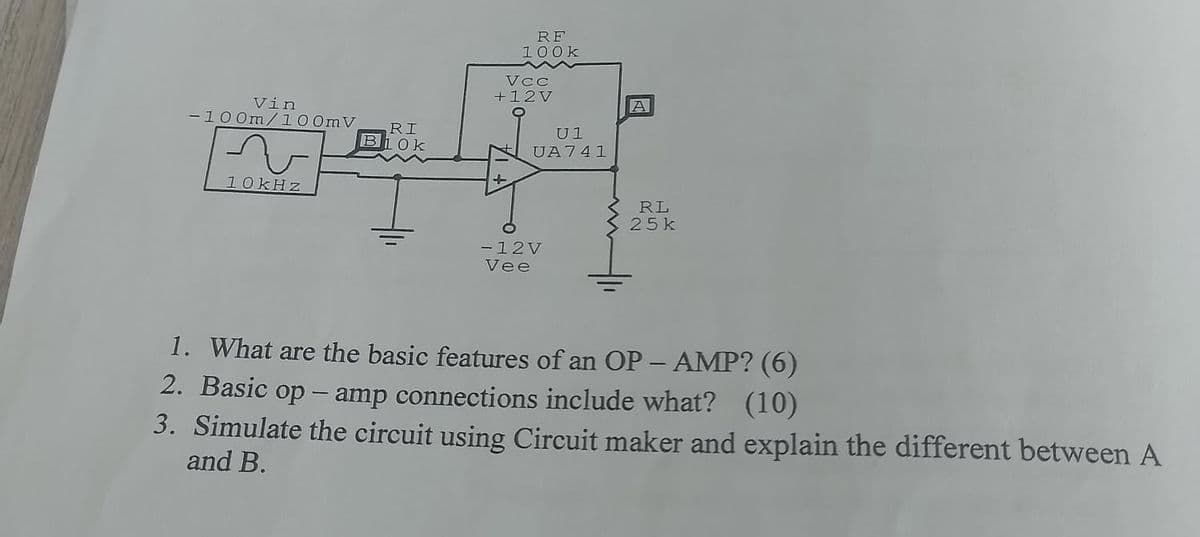
Vin -100m/100mV. 10kHz RI B10k RF 100k Vcc +12V U1 UA741 A RL 25k -12V Vee 1. What are the basic features of an OP-AMP? (6) 2. Basic op-amp connections include what? (10) 3. Simulate the circuit using Circuit maker and explain the different between A and B.
Q: 6.2 Include a synchronous clear input to the register circuit of Fig. 6.2. The modified register…
A: Step 1: Step 2:
Q: 3.- For the circuit in Fig. 3, calculate the firing angle at such that the continuous component of…
A: Step 1: Step 2:
Q: Determine the Thevenin equivalent of the circuit (impedance and voltage) across terminals a-b. The…
A: Step 1: Step 2: Step 3: Step 4:
Q: Solve and show illustration A 20-kW 127.4 -V separately excited dc machine is operated at a…
A: Step 1:
Q: Name three (3) ways in which you can improve the energy efficiency in combustion systems
A: Three methods for increasing energy efficiency in combustion systems include: 1. Use of…
Q: Please answer in typing format
A: Step 1: As instructed in question, after removing 50 ohms resistor and connecting 100 ohm between a…
Q: 1. Find norton equivalent circuit about a,b 30 is 2 ΚΩ 5 ΚΩ 10 ΚΩ + 40 V 5 20 ΚΩ 50 ΚΩ 40 ΚΩ
A:
Q: A 110-V, three-phase, Y-connected, %pole, 48-slot, 6000-rpm, double-layerwound, synchronous…
A: To find the flux per pole, we need to use the formula for synchronous generator voltage regulation…
Q: Suppose X and Y have the following joint PDF: [√c²-u²-v², if u≥0, v≥0, u² + v² ≤c² fxy (u,v) = 0.…
A: Hope you got your answer, if any query then raise it.Kindly do rate this helpful.....Thank You
Q: A shunt machine has armature and field resistances of 0.04 2 and 100 2 respectively. When connected…
A:
Q: Exercise 5 Find 11, 12 and ID2 in the circuit below. E 20 V 2 D1 Si ID2 R₁ R₂ D2 ▼ Si V₁ 3.3 ΚΩ 5.6…
A: Step 1: Basic concept Step 2: Solution page 1Step 3: Solution page 2
Q: I need help with this part please
A:
Q: 7. The main advantage of STTL over TTL is- that transistors in STTL 8. One way to reduce the power…
A: 7).
Q: Help
A: Step 1: For maximum power transfer theorem the load resistance is equal to equivalent resistance of…
Q: The inputs are A and B. Convert this diagram to an alphanumeric state diagram.
A: Imagine a machine that can be in specific situations and reacts differently based on what it…
Q: Calculate the RMS value of the load current (in amperes) at load L2 (compressor/motor pumps), and…
A: CONSIDERING SINGLE PHASE CONSIDERING THREE PHASE
Q: With the aid of a circuit diagram, show that two wattmeters can be connected to read the total power…
A: Step 1:Step 2:
Q: 15105 14310 13510 Solve the following problems. Show the complete solutions in 4 decimal places.…
A: 1. 2.3. 4.
Q: The electric field of an electromagnetic wave propogating in air is givenby E(z, t) = (4 cos ((6 ×…
A:
Q: me: JASTINE P. MABUTOL Long Examination in AC Apparatus Date: APRIL 23 Score: Tections: Solve the…
A: Step 1:Step 2:Step 3:Step 4:Step 5:Step 6:
Q: Calculate the convolution for the following tow functions f(t) & x(t)? x(t) (a) 2 1 2 2
A: First i write the function of f(t) and x(t) f(t)={2−t0for 0≤t≤2otherwise x(t)={10for…
Q: The circuit was in steady state for a long time before the switch was closed. Please calculate Vc₂…
A: Step 1:Step 2:
Q: Please answer in typing format
A: Let's solve the given problem step by step:Given:- \( R = 100 \ Ω \)- \( V_2 = 10 \ V \)- \( I_z =…
Q: Q4: For the Figure 2 consider the forward path transfer function as G(s) =2/s(s + 2) with a unity…
A: Here's a breakdown of how it might work and how to solve for the output voltage (Vout):Component…
Q: Please answer in typing format
A: The resistor draws a current of 0.0267 A and consumes an average power of 0.00113 W. Over 113 hours,…
Q: Help step by step
A: Step 1:When applying superposition theorem we replace another voltage source with short and current…
Q: Name two characteristics that energy efficiency improvements have?
A: ANS:Energy efficiency improvements reduce energy consumption and save costs, making processes more…
Q: 1- Write the output expression for each circuit as it appears in Fig.(6- 11) and then change each…
A: Step 1: Step 2: Step 3: Step 4:
Q: 5.17. A wave-wound dc machine has 4 poles, 71 slots, and 2 turns per coil. The armature radius is…
A:
Q: Please answer in typing format
A: Step 1:Step 2:Step 3:
Q: Needs Complete solution with 100 % accuracy.
A: I can't access the specific image you sent to provide a 100% accurate solution. However, I can…
Q: Needs Complete solution with 100 % accuracy.
A: Based on the image you sent, it appears to be a circuit diagram for a differential amplifier. Here's…
Q: 2021-2022 Q1 A voltmeter is always connected in parallel with the element being measured, and…
A: Based on the image you sent, it appears to be a circuit diagram with a voltage source (Vbat) and…
Q: Example (HW) (a). Calculate the voltage Ve using the voltage divider rule. (6). Calculate the…
A: Step 1: Step 2: Step 3: Step 4:
Q: Hi, can you help me to find out why I'm not getting the right result? (see my work attached). I…
A: The equation is supposed to be a quadratic equation in w. The red part in the equation will have two…
Q: Q3: A plant has a nominal model given by G(s) = 1 S(S+1)(1+2s) assume that this plant is to be…
A: Step 1: Step 2: IF YOU HAVE ANY DOUBT YOU CAN COMMENT HERE THANKS
Q: b. D latch with active-low enable signal. Clk D Q D D Q Clk E Qb
A: Step 1:Given D latch is a active low enable latch so when E= 0 ,Q=D, when E= 1,,Q= Memory State.…
Q: 2. Calculate the phase and line currents in the three-phase circuit given below, where Va = 202 40°…
A: The objective of the question is to calculate the phase and line currents in a three-phase circuit.…
Q: Please help with this parctice problem so I may study
A: based on your description of the circuit being a voltage regulator with a Zener diode and a BJT,…
Q: Please answer in typing format
A: Detailed explanation:a. The turns ratio of the transformer is 2:1. This means that for every 2 turns…
Q: Q2: Calculate the Fourier Transform F(w) for the following function f(t) = {1}] 0<t<6 otherwise
A:
Q: Q.1: Find the Fourier Transform F(w) for the following signals: f(t) 1.6 -3 -2 0 2 3
A:
Q: Here A= 18,B=16 please answer in typing format
A:
Q: The capacitor in the below circuit was discharged prior to assembly and the circuit was in steady…
A: Based on the image you sent, the circuit appears to be a voltage divider circuit with an additional…
Q: Definitions and examples▪ Global horizontal irradiance▪ Normal direct irradiance▪ Horizontal diffuse…
A: All these terms are related to understanding how much sunlight actually reaches a solar panel, which…
Q: using the following figure, if the voltage across R1 is 2.7∠ − 40° Vp and the voltage across L1 is…
A: Step 1: In the given circuit, there are three elements which are connected in series.Step 2: Apply…
Q: None
A: Sure, I can help you with the three-phase bridge inverter problem you sent. Here's how to solve for…
Q: Don't use chatgpt
A: Step 1:Step 2:Step 3: Step 4:
Q: Please answer in typing format
A:
Q: Answer all parts of the questions. Giving a numerical result without showing supporting work may…
A:
Trending now
This is a popular solution!
Step by step
Solved in 2 steps with 5 images
- Given a inverting op-amp with Vin= 1Vpk,1kHz and Rin=1kΩ , Rf=2kΩ, VEE=-5V, VCC= 5V, Explain the output waveform, voltage gain, and it's phase of the circuit.An ideal op-amp circuit is shown above, with dc supply Vcc = -Vcc = 12V.Assume that v1 = 2V, v2 = 2V, R1 = 3Ω, R2 = 3Ω. Please determine Rf (in ohm's) so that the output voltage vo = -10 volts.Q2/B)- Show the connection of three combination op-amp stages ( Parallel and series connection) using an LM348 IC to provide outputs that are 110, 400, and 2601 times larger than the input. Use a feedback resistor of Rf = 500 k? in all stages, while can use only (R= 50 k? for first stage), (R= 25 k? for second stage), and (R= 10 k? for third stage
- What must the voltage at the inverting input of the op-amp be? What is the voltage drop across Rin? What is the input current, iin, through Rin? What is the output voltage vout?10 V(p-p),1KHz sinusoidal voltage is applied to op-amp input and non-inverting input isgrounded. What is the gain of this op-amp and why?Using any number of Op-Amps, design multistage amplifier to amplify input Ac signal with 0.01V amplitude, the expected output voltage would have 4V amplitude. The input signal frequency = 10 KHz. Assume gain bandwidth product of Op-Amp = 1 MHz
- Q4/A)- Show the connection of three combination op-amp stages using an LM348 IC to provide outputs that are 110, 1681, and 420 times larger than the input. Use a feedback resistor of Rf = 400 k? in all stages, while can use only (R= 40 k? for first stage), (R= 10 k? for second stage), and (R= 20 k? for third stagedraw the block diagram of op-AmpTell the ideal char. of op-amp.
- solve 4 Use a BJT op-amp)1 You’ve been asked to build an alarm system using monstable multvibrator having an activetime pf 100msec.. Explain the principle of operation and the type feedback of the op-amp.What is the advantage of this circuit?2 You’ve been asked to build a low frequency square wave generator using a basic comparatorhaving a frequency of 10kHz and 50% duty cycle. Explain the principle of operation and thetype of feedback of the op-amp. What is the advantage of this circuit?3 Build a Wein-Bridge oscillator using, C=1µF and +10V power supply to produce 10 kHzsinusoidal waveform. Generate your plots and compare output results. Highlight anydiscrepancies and discuss what happens if we want to increase the frequency to 100 kHz.4 Build a high frequency Colpitts oscillator producing 10kHz Discuss its advantage over RCoscillators. How can you modify the circuit to include a crystal in you circuit. What is atypical application of such an oscillator?Q1. A series Op-Amp voltage regulator which its input voltage is 15V and to regulate output voltage of 8V Draw the circuit diagram for the series regulator Analyse the circuit to choose the proper used components Calculate the line regulation in both % and in %/V for the circuit if the input voltage changes by an amount of 3V which leads to a change in output voltage of 50mVIn the figure a series voltage regulator circuit is shown. Design the value of R1, R2 and R of the voltage regulator when an 8 V Zener diode is used to maintain a regulated output voltage, VL, of 20 V. Assume that the unregulated input varies between 18 V and 22 V, and that the Op-Amp is ideal. The minimum Zener current needed to keep it in breakdown is 10 mA.(need only handwritten solution .otherwise downvote.)