
Introductory Circuit Analysis (13th Edition)
13th Edition
ISBN: 9780133923605
Author: Robert L. Boylestad
Publisher: PEARSON
expand_more
expand_more
format_list_bulleted
Related questions
Question

Transcribed Image Text:Task 4: Ring oscillator
An a-stable multivibrator oscillates automatically between two semi-stable states. It has no stable
states. There are different ways of construct a-stable multivibrators, but the type of multivibrator used
here is a ring oscillator. The rate of oscillation is determined by the propagation delays of the
components.
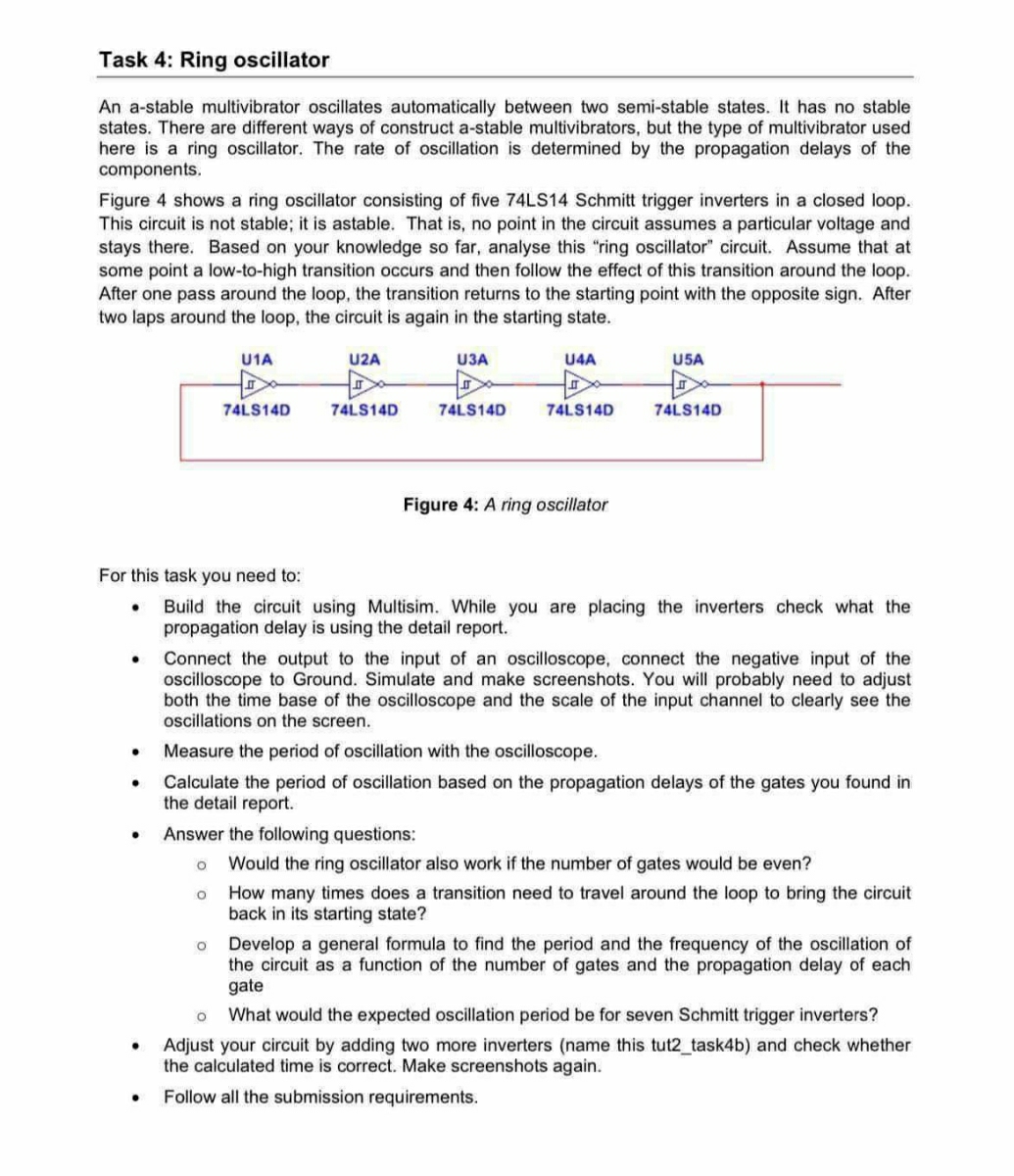
Figure 4 shows a ring oscillator consisting of five 74LS14 Schmitt trigger inverters in a closed loop.
This circuit is not stable; it is astable. That is, no point in the circuit assumes a particular voltage and
stays there. Based on your knowledge so far, analyse this "ring oscillator circuit. Assume that at
some point a low-to-high transition occurs and then follow the effect of this transition around the loop.
After one pass around the loop, the transition returns to the starting point with the opposite sign. After
two laps around the loop, the circuit is again in the starting state.
U1A
U2A
U3A
U4A
U5A
74LS14D
74LS14D
74LS14D
74LS14D
74LS14D
Figure 4: A ring oscillator
For this task you need to:
.
•
•
Build the circuit using Multisim. While you are placing the inverters check what the
propagation delay is using the detail report.
Connect the output to the input of an oscilloscope, connect the negative input of the
oscilloscope to Ground. Simulate and make screenshots. You will probably need to adjust
both the time base of the oscilloscope and the scale of the input channel to clearly see the
oscillations on the screen.
Measure the period of oscillation with the oscilloscope.
Calculate the period of oscillation based on the propagation delays of the gates you found in
the detail report.
Answer the following questions:
。 Would the ring oscillator also work if the number of gates would be even?
。 How many times does a transition need to travel around the loop to bring the circuit
back in its starting state?
Develop a general formula to find the period and the frequency of the oscillation of
the circuit as a function of the number of gates and the propagation delay of each
gate
。 What would the expected oscillation period be for seven Schmitt trigger inverters?
Adjust your circuit by adding two more inverters (name this tut2_task4b) and check whether
the calculated time is correct. Make screenshots again.
Follow all the submission requirements.
Expert Solution
This question has been solved!
Explore an expertly crafted, step-by-step solution for a thorough understanding of key concepts.

Step by stepSolved in 2 steps with 3 images

Knowledge Booster

Similar questions
Recommended textbooks for you
- Introductory Circuit Analysis (13th Edition)Electrical EngineeringISBN:9780133923605Author:Robert L. BoylestadPublisher:PEARSON
 Delmar's Standard Textbook Of ElectricityElectrical EngineeringISBN:9781337900348Author:Stephen L. HermanPublisher:Cengage Learning
 Programmable Logic ControllersElectrical EngineeringISBN:9780073373843Author:Frank D. PetruzellaPublisher:McGraw-Hill Education
  Fundamentals of Electric CircuitsElectrical EngineeringISBN:9780078028229Author:Charles K Alexander, Matthew SadikuPublisher:McGraw-Hill Education
 Electric Circuits. (11th Edition)Electrical EngineeringISBN:9780134746968Author:James W. Nilsson, Susan RiedelPublisher:PEARSON
 Engineering ElectromagneticsElectrical EngineeringISBN:9780078028151Author:Hayt, William H. (william Hart), Jr, BUCK, John A.Publisher:Mcgraw-hill Education,
Introductory Circuit Analysis (13th Edition)
Electrical Engineering
ISBN:9780133923605
Author:Robert L. Boylestad
Publisher:PEARSON
Delmar's Standard Textbook Of Electricity
Electrical Engineering
ISBN:9781337900348
Author:Stephen L. Herman
Publisher:Cengage Learning
Programmable Logic Controllers
Electrical Engineering
ISBN:9780073373843
Author:Frank D. Petruzella
Publisher:McGraw-Hill Education
Fundamentals of Electric Circuits
Electrical Engineering
ISBN:9780078028229
Author:Charles K Alexander, Matthew Sadiku
Publisher:McGraw-Hill Education
Electric Circuits. (11th Edition)
Electrical Engineering
ISBN:9780134746968
Author:James W. Nilsson, Susan Riedel
Publisher:PEARSON
Engineering Electromagnetics
Electrical Engineering
ISBN:9780078028151
Author:Hayt, William H. (william Hart), Jr, BUCK, John A.
Publisher:Mcgraw-hill Education,