Elements Of Electromagnetics
7th Edition
ISBN: 9780190698614
Author: Sadiku, Matthew N. O.
Publisher: Oxford University Press
expand_more
expand_more
format_list_bulleted
Concept explainers
Question

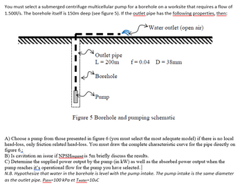
Transcribed Image Text:You must select a submerged centrifuge multicellular pump for a borehole on a worksite that requires a flow of
1.500l/s. The borehole itself is 150m deep (see figure 5). If the outlet pipe has the following properties, then:
wwww
wwwwwww
Water outlet (open air)
wwww
Outlet pipe
L = 200m
Borehole
wwwww
Pump
f= 0.04 D = 38mm
Figure 5 Borehole and pumping schematic
A) Choose a pump from those presented in figure 6 (you must select the most adequate model) if there is no local
head-loss, only friction related head-loss. You must draw the complete characteristic curve for the pipe directly on
figure 6.;
B) Is cavitation an issue if NPSHrequired is 5m briefly discuss the results.
C) Determine the supplied power output by the pump (in kW) as well as the absorbed power output when the
pump reaches it's operational flow for the pump you have selected. |
N.B. Hypothesize that water in the borehole is level with the pump intake. The pump intake is the same diameter
as the outlet pipe. Patm-100 kPa et Twater=100C
![350
H[m]
300
250
200
150
100
[%]4
50
og
60
50
40
30
20
0
0
0.0
"
1
"
L
"
L
"
I
to
I
1
1
I
+
+
5
I
"
"
A
F
"
I
4
++
II
T
"
I
I
I
I
2
0.5
10
"
10
T
fr
T
4
"
"
15
8GS75
8GS75R
8GS55
8GS55R
8GS40
8GS30
8GS22
8GS15
8GS11
8GS07
1.0
4
20
20
1.5
25
30
2.0
30
40
2.5
35
7.1%)
10
40 Q[imp gpm]
Q[US gpm]
3.0
1100
1000
900
800
700
600
[24] H
500
400
300
200
100
0
Q[m³/h]
Q[/s]
Extrait du Catalogue technique: pompes et systèmes de pompage pour le génie climatique, l'adduction, la surpression d'Eau et le relevage des
eaux usées .p.621
Figure 6 Pump characteristic curves and efficiency curve](https://content.bartleby.com/qna-images/question/f202e907-5449-4d59-a324-7d6009f3a6a2/d38fdf41-07d3-4a32-91ba-d72ba7399387/h8defp_thumbnail.png)
Transcribed Image Text:350
H[m]
300
250
200
150
100
[%]4
50
og
60
50
40
30
20
0
0
0.0
"
1
"
L
"
L
"
I
to
I
1
1
I
+
+
5
I
"
"
A
F
"
I
4
++
II
T
"
I
I
I
I
2
0.5
10
"
10
T
fr
T
4
"
"
15
8GS75
8GS75R
8GS55
8GS55R
8GS40
8GS30
8GS22
8GS15
8GS11
8GS07
1.0
4
20
20
1.5
25
30
2.0
30
40
2.5
35
7.1%)
10
40 Q[imp gpm]
Q[US gpm]
3.0
1100
1000
900
800
700
600
[24] H
500
400
300
200
100
0
Q[m³/h]
Q[/s]
Extrait du Catalogue technique: pompes et systèmes de pompage pour le génie climatique, l'adduction, la surpression d'Eau et le relevage des
eaux usées .p.621
Figure 6 Pump characteristic curves and efficiency curve
Expert Solution
This question has been solved!
Explore an expertly crafted, step-by-step solution for a thorough understanding of key concepts.
Step by stepSolved in 5 steps with 2 images

Follow-up Questions
Read through expert solutions to related follow-up questions below.
Follow-up Question
I can't see the right side of the answer

Transcribed Image Text:1 L = 10³ m³ Depth of the boi
lying Bernoulli's equation at 1 and

Transcribed Image Text:stem and pun
= H₂ + H₂ - HL:
selectedB As,
Solution
by Bartleby Expert
Follow-up Questions
Read through expert solutions to related follow-up questions below.
Follow-up Question
I can't see the right side of the answer

Transcribed Image Text:1 L = 10³ m³ Depth of the boi
lying Bernoulli's equation at 1 and

Transcribed Image Text:stem and pun
= H₂ + H₂ - HL:
selectedB As,
Solution
by Bartleby Expert
Knowledge Booster
Learn more about
Need a deep-dive on the concept behind this application? Look no further. Learn more about this topic, mechanical-engineering and related others by exploring similar questions and additional content below.Similar questions
- Please answer in accurate solutionarrow_forwardDo not provide Ai solutionarrow_forwardCS) Flow through a heat exchanger tube is to be studied by means of a 1/10 scale model. If the tmateaangeraarmall, carries widecreme de ratio of pressure losses between the model and the prototype if water is used in the model.arrow_forward
- show all working out pleasearrow_forwardFor a 6.25-inch Model 4075 pump operated at 1160 rpm, if 450 GPM of water is to be delivered, what will be the estimated pump head in ft? HEAD IN FEET 30 25 0 0 0 10 O 6 ft 7.25" (184mm) 20 7.00" (178mm). 6.75" (171mm). 6.50" (165mm)] 15 6.25" (159mm). 5 O 16 ft O 20 ft O 12 ft aco® L/SEC 5 OT 10 Model 4075 FI & CI Series 15 -6-6 ⁰ dº 20 ANA 888 778 25 REQUIRED NPSH do 1160 RPM November 1, 2010 K ・dº- [M 90 do 30 8800 81 1HP(.75KW) DeJ kin do 60% 35 do 50 Curve no. 2175 Min. Imp. Dia. 6.25" Size 5 x 4 x 7.0 40 45 3HP(2.2KW), 2HP(1 5KW) 5HP(1 1KW)> CURVES BASED ON CLEAR WATER WITH SPECIFIC GRAVITY OF 1.0 L 75 150 225 300 375 450 525 600 675 FLOW IN GALLONS PER MINUTE NOWONG FEET 15 12 7 6 2 1 NPSH 758 50 5 HEAD IN METERS 45 586888 KPO 60 40 20 10 LO HEAD IN KILOPASCALSarrow_forwardQuiqarrow_forward
- a 4 Exercise 7 -Opening and closing a boiler door for b) Calculate retracting speed, retracting time, travel speed ratio and travel time ratio. ictin Characteristic data required for calculation: Piston surface area: Ap = 2.0 sq. cm Piston ring surface area: APR = 1.2 sq. cm Stroke length: = 200 mm S Pump delivery rate: = 2 l/min b Retracting speed Retracting time Travel speed ratio Travel time ratioarrow_forwarda) Develop an equation for the head (in ft) developed by the pump described by the chartas a function of flow rate (in gpm) when the pump uses a 9 ¾” impeller. b) Develop an equation for the pump efficiency as a function of flow rate (gpm) when the pump uses a 9 ¾” impeller.arrow_forward### Develop a conclusion of a piping design report for the choice of a pump, based on the calculated parameters of flow Q = 10 l/s, power of 10kw taking into account that the head of 60 mca adopted was higher than that calculated for safety, and that the pump was chosen through the WebCAPS catalogue of the company GRUNDFOS. The pump chosen was the GRUNDFOS CR 32-3 A-F-A-E-HQQEarrow_forward
arrow_back_ios
arrow_forward_ios
Recommended textbooks for you
 Elements Of ElectromagneticsMechanical EngineeringISBN:9780190698614Author:Sadiku, Matthew N. O.Publisher:Oxford University Press
 Mechanics of Materials (10th Edition)Mechanical EngineeringISBN:9780134319650Author:Russell C. HibbelerPublisher:PEARSON
 Thermodynamics: An Engineering ApproachMechanical EngineeringISBN:9781259822674Author:Yunus A. Cengel Dr., Michael A. BolesPublisher:McGraw-Hill Education
 Control Systems EngineeringMechanical EngineeringISBN:9781118170519Author:Norman S. NisePublisher:WILEY
 Mechanics of Materials (MindTap Course List)Mechanical EngineeringISBN:9781337093347Author:Barry J. Goodno, James M. GerePublisher:Cengage Learning
 Engineering Mechanics: StaticsMechanical EngineeringISBN:9781118807330Author:James L. Meriam, L. G. Kraige, J. N. BoltonPublisher:WILEY

Elements Of Electromagnetics
Mechanical Engineering
ISBN:9780190698614
Author:Sadiku, Matthew N. O.
Publisher:Oxford University Press

Mechanics of Materials (10th Edition)
Mechanical Engineering
ISBN:9780134319650
Author:Russell C. Hibbeler
Publisher:PEARSON

Thermodynamics: An Engineering Approach
Mechanical Engineering
ISBN:9781259822674
Author:Yunus A. Cengel Dr., Michael A. Boles
Publisher:McGraw-Hill Education

Control Systems Engineering
Mechanical Engineering
ISBN:9781118170519
Author:Norman S. Nise
Publisher:WILEY

Mechanics of Materials (MindTap Course List)
Mechanical Engineering
ISBN:9781337093347
Author:Barry J. Goodno, James M. Gere
Publisher:Cengage Learning

Engineering Mechanics: Statics
Mechanical Engineering
ISBN:9781118807330
Author:James L. Meriam, L. G. Kraige, J. N. Bolton
Publisher:WILEY