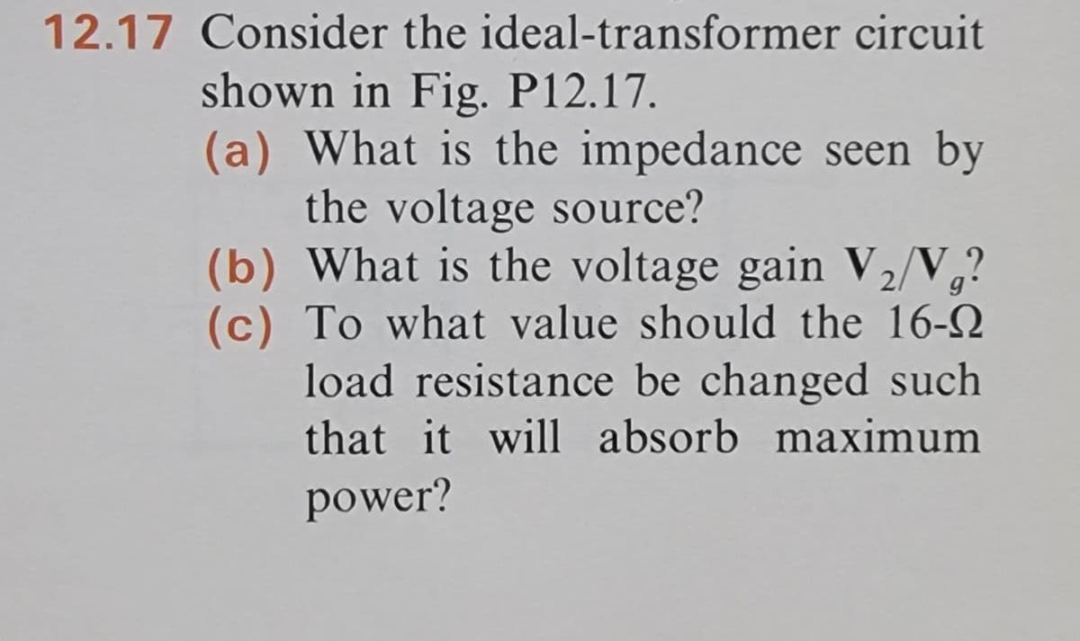
Consider the ideal-transformer circuit shown in Fig. P12.17. (a) What is the impedance seen by the voltage source? (b) What is the voltage gain V₂/V₁? (c) To what value should the 16-0 load resistance be changed such that it will absorb maximum power?
Consider the ideal-transformer circuit shown in Fig. P12.17. (a) What is the impedance seen by the voltage source? (b) What is the voltage gain V₂/V₁? (c) To what value should the 16-0 load resistance be changed such that it will absorb maximum power?

Power System Analysis and Design (MindTap Course List)
6th Edition
ISBN:9781305632134
Author:J. Duncan Glover, Thomas Overbye, Mulukutla S. Sarma
Publisher:J. Duncan Glover, Thomas Overbye, Mulukutla S. Sarma
Chapter2: Fundamentals
Section: Chapter Questions
Problem 2.18P: Let a series RLC network be connected to a source voltage V, drawing a current I. (a) In terms of...

Related questions

Question
Please solve the following problem showing all steps and necessary explanations. This problem is just for practice and not for a grade but it would be very helpful. Thank you for your time!
Transcribed Image Text:12.17 Consider the ideal-transformer circuit
shown in Fig. P12.17.
(a) What is the impedance seen by
the voltage source?
(b) What is the voltage gain V₂/V₁?
(c) To what value should the 16-
load resistance be changed such.
that it will absorb maximum
power?

Transcribed Image Text:Ug
+ 1
3 Ω
Fig. P12.17
1:4
+
U2
16Ω
Expert Solution
This question has been solved!
Explore an expertly crafted, step-by-step solution for a thorough understanding of key concepts.

This is a popular solution!

Trending now
This is a popular solution!

Step by step
Solved in 5 steps with 4 images

Knowledge Booster


Learn more about
Need a deep-dive on the concept behind this application? Look no further. Learn more about this topic, electrical-engineering and related others by exploring similar questions and additional content below.Recommended textbooks for you
Power System Analysis and Design (MindTap Course …
Electrical Engineering
ISBN:
9781305632134
Author:
J. Duncan Glover, Thomas Overbye, Mulukutla S. Sarma
Publisher:
Cengage Learning
Power System Analysis and Design (MindTap Course …
Electrical Engineering
ISBN:
9781305632134
Author:
J. Duncan Glover, Thomas Overbye, Mulukutla S. Sarma
Publisher:
Cengage Learning