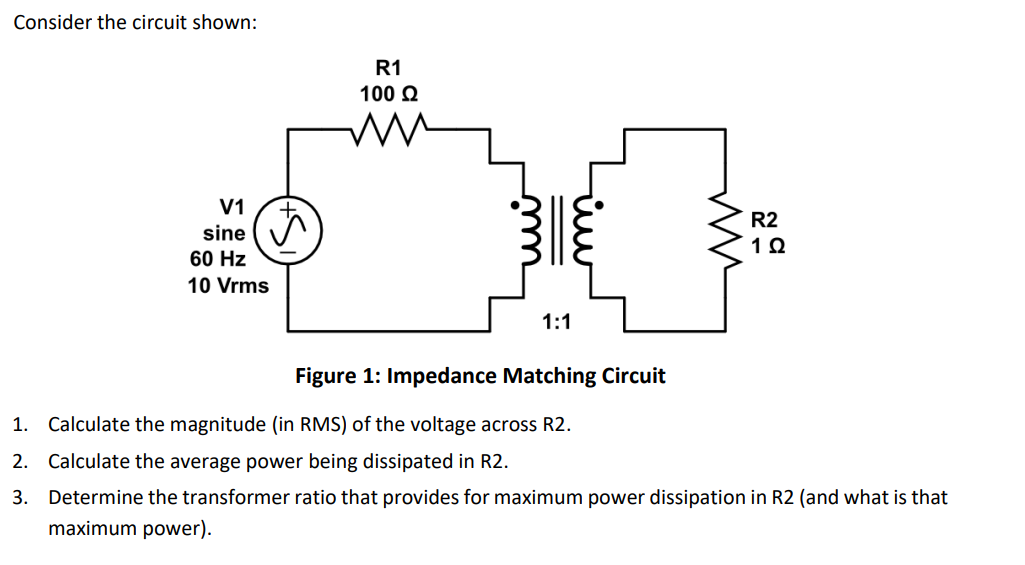
Consider the circuit shown: R1 100 Ω V1 sine ☑ 60 Hz 10 Vrms 1:1 سنا ли R2 1 Ω Figure 1: Impedance Matching Circuit 1. Calculate the magnitude (in RMS) of the voltage across R2. 2. Calculate the average power being dissipated in R2. 3. Determine the transformer ratio that provides for maximum power dissipation in R2 (and what is that maximum power).


Q: You are handed a black box containing a circuit with two terminals marked a and b. With nothing else…
A: Thevenin voltage is 15 V, the Thevenin resistance is 0.4 ohms, and the resistance of the external…
Q: 7.8.50 Use source transformation to find V, in the circuit in Fig. P7.8.50. 2/0°A 50 4/0°V w 202 ΖΩ…
A:
Q: Using Mesh analysis find Vo in the circuit. 60 ww 492 60 V 20 Ω www 20 Ω +1 5%
A: In this question, we need to determine the voltage Vo using the mesh analysis.
Q: For the electric circuit shown below, find i for >0 when the switch is open (as shown in the…
A: In the given question we need to calculate the current i flow through 12 ohm resistor.
Q: (A) Explain in details whether or not the following signal is periodic. In case it is periodic,…
A: In this question, we need to determine the fundamental time period if signal is periodic. Check…
Q: Im not sure how to use convolution for this. Thank You!
A: if you have any doubt please ask :)Explanation:Step 1: Step 2: Step 3: Step 4:
Q: Calculate the short circuit current. Upload your file showing your calculations and answer. 100 kVA,…
A: Given ratings of the shown figure100 kVA, 1-Ph Transformer, 2% Z, 120/240 VNegligible Distance600 A…
Q: Please answer in typing format
A: The circuit diagram,
Q: Retrieval: Does time-varying mag. field always produce time-varying elect. field? B ய Time Time
A: The given graph is shown below,
Q: Q2. Consider a unity-feedback system whose open-loop transfer function is: Y G(s) = R(S)= Ke-0.8s…
A:
Q: Assume that the circuit in the figure has L equal to 0.700 H. R equal to 450 92, and C equal to 3.50…
A:
Q: Given the circuit shown below, and the input signal, determine the output signal. Vi(t) + +1 + Vc(t)
A:
Q: L₁ B R₁ C₁ L2 b Given the element values R1 = 70 92, L1 = 50 mH, L2 = 110 mH and 4398.23, find the…
A: The given circuit isR1=70 Ω.L1=50 mH.L2=110 mH.ω=4398.23 rad/s.We need to determine the value of C1…
Q: Prove that the following circle is unbalanced Wheatstone bridge, and How to R4 =110 Q and R3= 1900…
A: We are given,R1=480ΩR2=90ΩR3=190ΩR4=110Ωprove that the wheatstone bridge is unbalance and hou to…
Q: The switch in the circuit in (Figure 1) has been closed for a long time. At t = 0, the switch is…
A: In the given question we need to calculate the expression of Vo and Io.
Q: (a) Find RL for maximum power transfer and the maximum power that can be transferred to the load in…
A: The circuit diagram,
Q: 5.2-3 In a satellite radio system, 500 stations of stereo quality are to be multiplexed in one data…
A: Please refer below page.Explanation:
Q: compute and sketch the convolution between following pair of signals: h[n] = (1/2)^n u[n-4], x[n] =…
A: The signals are given by⇒h[n]=(12)nu[n−4] ;⇒x[n]=4nu[2−n] ;We need to determine and sketch the…
Q: (a) Find Vo in the circuit shown below. ΠΩ ΖΩ ww 1Ω ww 10/0°V + ΠΩ ΠΩ 1Ω WWW V 0
A: Given:we need to find:the output voltage V0.
Q: Urgent!! Please write down all workings thank you! Answer: V1 = 0.928cos (10t - 86.142deg) mV V2…
A: V1 = 0.928cos (10t - 86.142deg) V V2 = 0.969cos (10t - 16.48deg) VI1 = 2.5 cos 10t mA I2 =…
Q: For the circuit below the switch has been closed a long time and opened at t=0. Find a. i(t) for t≥0…
A: The given circuit isWe need to determine the expressions of a. iL(t) for t≥0.b. i0(t) for t≥0+.c.…
Q: The waveform below from an RC or RL circuit represents time constant tau = ms. 8 7 6 v(t) 5 4 3 2 1…
A: In d.c. analysis, under steady state condition, the inductor will be behave as short circuit. When…
Q: V₁(t) + R1 www ix(t) C₁ R₂ Given the element values v₁ (t) = 18cos(210³t) V, R1 = 700 £2, R2 = 1400…
A: The given circuit isR1=700 Ω.R2=1400 Ω.C1=120 nF.The supply voltage is⇒v1(t)=18cos(2π103t), V.We…
Q: (HW) Q1: Calculate the real and reactive power absorbed by every element (including the sources) in…
A: The given circuit diagram is shown below,
Q: Q2) Using Laplace Transform solve the following equation: (Simplify and pretty the solution) -2y"…
A: The given equation is shown below..We need to find the Laplace transform.Since the initial…
Q: What is a voltage-controlled voltage source? How can build this type of circuit by using an op-amp?
A: A voltage-controlled voltage source (VCVS) is a type of dependent source that generates an output…
Q: ladder diagram for bottom half of a switched receptacle is to always be hot plus a duplex receptacle…
A: The objective of this question is to create a ladder diagram for a specific electrical wiring setup.…
Q: Question 3
A: 3.(a)The secondary current magnitude is 100A and the angle is 45∘ lagging. (b) The load impedance…
Q: please solve q3 if you cant do the matlab code its okay but i will appreciate it using the…
A: By using given z transform pairs and property of multiplication with n we can solve c part of this…
Q: A DC motor is fed with the armature voltage 430 V. At the current load, the speed is 180 rpm and the…
A: Given:Armature voltage (Va) = 430 VSpeed (n) = 180 rpmArmature current (Ia) = 29 AArmature…
Q: If the cost of electricity decreased to 8 ¢/kWh, which alternative would be the most cost-effective?…
A: 6.Given parameters decrease to 8¢/kWh7.given parameters alternative just break even
Q: i need matlab code for Convert the transfer function to state space in Jordan canonical form of…
A: The given transfer function is shown below..It is asked to write the MATLAB code to convert the…
Q: QUESTION 4 R C S Select the correct timing diagram for the gated S-R latch shown above. 1 3 t t CSRO…
A: In the given question we need to find the correct timing diagram.
Q: Find the Norton equivalent of the following circuit with respect to the terminals a and b. a) What…
A: Norton's Theorem states that any linear electrical network with multiple voltage and current sources…
Q: Please solve the question: Subject (Communication Systems) **_ {8(t)+u(t)—u(t−2)}dt Note: A question…
A: The integral becomes : 3 Two methods shown below to solve this problem.Explanation:Method 1:…
Q: (a) If an H winding and an X winding short together, the result will be this is a normal mode of…
A: (a) If an H winding and an X winding short together:High current flow and transformer failure:This…
Q: a b -b- A coil with a 10.800 cm and b = 13.000 cm is in the same plane with a long straight wire.…
A: We have,To calculate the emf in the loop at t=8 sec
Q: 20 0 йо -5 ▲i (mA) 4 6 8 t (ms)
A:
Q: List and describe the different types of lighting classes available on the market. Discuss the…
A: a. Residential Lighting: This class includes lighting fixtures and bulbs designed for use in homes,…
Q: ladder diagram for three circuits, circuit A is one lampholder and one duplex receptacle controlled…
A: According to the question, we need to design a ladder diagram for three circuits, circuit A is one…
Q: For the circuit below, solve the current through R3 and power dissipated from R3 Using a.Mesh…
A: Given:we need to find:the current through R3 and power dissipated from R3 using:a. Mesh analysis,b.…
Q: 2.4.3 Find the current Iд in the circuit in Fig. P2.4.3.
A: The given data is shown below:
Q: Show how to implement the sum-of-products circuit shown below using only NAND gates. Hint – use…
A: Please see the explanation Explanation:Step 1:
Q: The power applied to R1 is calculated theoretically (hand calculation) and the voltage and current…
A: In this question, we need to determine the power applied to the resistance R. Power applied to the…
Q: For each circuit provided, fully solve and complete the associated table.
A:
Q: 5.2-8 A signal bandlimited to 1 MHz is sampled at a rate 30% above the Nyquist rate and quantized…
A: A signal bandlimited to 1 MHz is sampled at a rate 30% above the Nyquist rate and quantized into…
Q: The waveforms are correct for the logic circuit shown. ADC X A B C O True O False X
A: The logic circuit is given byThe waveforms are given byWe need to tell whether the given waveforms…
Q: 20/0° V 10 Ω V₁ j40 V₂ 5 ww m -J2.50 21x Ans: Ix = 7.59 <108.4° A ell 12.52
A: Kirchhoff's Current Law (KCL) states that the total current entering a junction (or node) in an…
Q: A 110-V, three-phase, Y-connected, 8 pole, 48-slot, 6000-rpm, double- layer wound, synchronous…
A: “Since you have posted multiple questions, we will provide the solution only to the first question…
Q: Dry soil has a conductivity of 10 S/m, a relative permittivity of 3, and a relative permeability of…
A:
Give a solution to all the questions below

Step by step
Solved in 1 steps with 3 images

- Consider Figure 3.25 of the text for a transformer with off-nominal turns ratio. (i) The per-unit equivalent circuit shown in part (c) contains an ideal transformer which cannot be accommodated by some computer programs. (a) True (b) False (ii) In the - circuit representation for real c in part (d), the admittance parameters Y11 and Y12 would be unequal. (a) True (b) False (iii) For complex c, can the admittance parameters be synthesized with a passive RLC circuit? (a) Yes (b) NoFor the circuit element of Problem 2.3, calculate (a) the instantaneous power absorbed, (b) the real power (state whether it is delivered or absorbed). (c) the reactive power (state whether delivered or absorbed). (d) the power factor (state whether lagging or leading). [Note: By convention the power factor cos() is positive. If | | is greater than 90, then the reference direction for current may be reversed, resulting in a positive value of cos() ].A two-winding single-phase transformer rated 60kVA,240/1200V,60Hz, has an efficiency of 0.96 when operated at rated load, 0.8 power factor lagging. This transformer is to be utilized as a 1440/1200-V step-down autotransformer in a power distribution system. (a) Find the permissible kVA rating of the autotransformer if the winding currents and voltages are not to exceed the ratings as a two-winding transformer. Assume an ideal transformer. (b) Determine the efficiency of the autotransformer with the kVA loading of part (a) and 0.8 power factor leading.
- A single-phase 100-kVA,2400/240-volt,60-Hz distribution transformer is used as a step-down transformer. The load, which is connected to the 240-volt secondary winding, absorbs 60 kVA at 0.8 power factor lagging and is at 230 volts. Assuming an ideal transformer, calculate the following: (a) primary voltage, (b) load impedance, (c) load impedance referred to the primary, and (d) the real and reactive power supplied to the primary winding.An infinite bus, which is a constant voltage source, is connected to the primary of the three-winding transformer of Problem 3.53. A 7.5-MVA,13.2-kV synchronous motor with a sub transient reactance of 0.2 per unit is connected to the transformer secondary. A5-MW,2.3-kV three-phase resistive load is connected to the tertiary Choosing a base of 66 kV and 15 MVA in the primary, draw the impedance diagram of the system showing per-unit impedances. Neglect transformer exciting current, phase shifts, and all resistances except the resistive load.Consider Figure 3.4. For an ideal phase-shifting transformer, the imda nce is unchanged when it is referred from one side to the other. (a) True (b) False
- The transformer of Problem 3.16 is supplying a rated load of 50 kVA at a rated secondary voltage of 240 V and at 0.8 posr factor lagging. Neglect the transformer exciting current. (a) Determine the input terminal voltage of the transformer on the high-voltage side. (b) Sketch the corresponding phasor diagram. (c) If the transformer is used as a step-down transformer at the load end of a feeder whose impedance is 0.5+j2.0, find the voltage VS and the power factor at the sending end of the feeder.A 50 MVA, 11/132 kV three-phase, 50 Hz, generator transformer has guaranteed parameters as, load loss 160 kW at full load at 75°C, no load loss 30 kW and percentage reactance 9% at rated load. Calculate the following:*percentage regulation a full load and unity power factor*percentage regulation at 3/4 load and 0.85 lagging power factor*efficiency at full load and unity power factor*efficiency at 3/4 load and 0.85 lagging power factor(Use 5 decimal places)The following data were obtained from a short-circuit test performed upon a 50 kVA, 2300/115 V, 60 Hz transformer: Esc = 87 V, Isc = 21.75 A, Psc = 590 W. Calculate (a) equivalent resistance, reactance and impedance referred to the primary, and (b) voltage regulation at a power factor of 0.866 lagging. Subject: Electrical Apparatus and Devices
- Which termination would result to a phase change of 180 degrees at the load if Zo = 100 ohm? a. 50 ohm b. short circuit c. 75 ohm d. all of these What is the purpose of impedance matching? a. maximum return loss b. maximum SWR c. maximum load power d. maximum reflection A short piece of transmission line that may be open or shorted and used for impedance matching purposes. a. converter b. decoder c. stub d. transformerData from short-circuit and open-circuit tests of a 25-kVA, 6900-230 V, 60 Hz transformer are given in table below: Sr No Open circuit parameters VOC = 230 IOC = 5.4 A POC = 260 W Short circuit parameters VSC = 513 ISC = 3.6 A PSC = 465 W Determine: (i) The magnetizing reactance referred to the high side (ii) The per unit parameters (iii) Efficiency (iv) Voltage regulation at 0.65 per unit load and 85% power factor leading (v) Low side voltage when the load is removed (vi) Voltage that must be applied to the primary in order to obtain the low side voltage in the part (v)A two-winding transformer rated at 100 kVA, is connected as an autotransformer to provide 10kV from a 15kV supply. Calculate the new rated kVA output. consider the power transformer mode and calculate the related currents Where, Vp = 10000VIp = S/(√3Vp) Is = S/(√3Vs) When find the new currents and voltages proceed to find the primary and secondary powers of the autotransformer. And conclude the rating of the autotransformer.