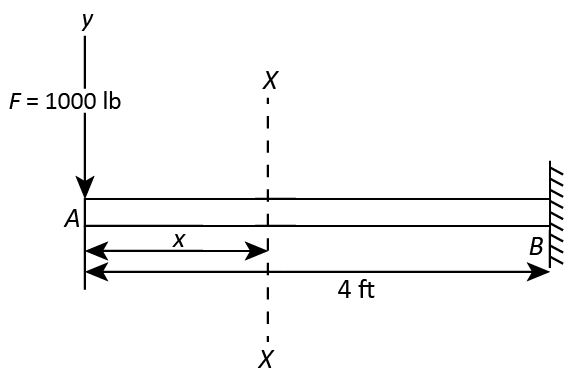
7-27 For the cantilever beam shown in Fig. P7-27, write equa- tipns for the shear force V, and the bending moment M, for any section of the beam in the interval 0
Q: Fig. 2 shows the shear force (KN) and bending moment (KNm) diagrams for the beam in Fig. 1. P- 120 e…
A: The situation of the beam is shown below.
Q: 1. Analyze the beam shown at section 1 (determine the internal force; moment and shear). P (kN) 36…
A:
Q: i) identify the boundary conditions for shear, moment and displacements. ii) using the equation of…
A:
Q: *RII-4. Determine the maximum bending stres in the handle of the cable cutter at section a-a. A…
A: For solution refer below images.
Q: For the simply supported beam subjected to the loading shown, derive equations for the shear force…
A:
Q: F7-3. Determine the internal normal force, shear force, and bending moment at point C in the beam.…
A: Draw the FBD of the given problem. Apply equilibrium condition. Determine the moment about point B.
Q: F1 F2 F3 F4 By C D (E A a b d
A: As per company's guidelines, we are allowed to answer only 3 sub parts. Kindly post remaining sub…
Q: The beam cross section shown below has been proposed for a short pedestrian bridge. The cross…
A:
Q: The bending moment acting on the triangular cross section of a beam is 3.6 kN m. Determine the…
A:
Q: Determine the internal normal force, shear force, and moment at point C, using the methods of…
A:
Q: If Ma- 68.5 kN-m and Mc- 56.0 kN-m, use the graphical method to construct the bending -moment…
A:
Q: Since the bending safety stress em = 10 MPa, shear safety stress em = 600 kPa of the rectangular…
A:
Q: 1. Neglecting transverse shear effect show the maximum moments and determine omax = (16/TD³)(M, +…
A: Given dataDiameter of the rod = DTo show the maximum moments and determine the maximum stress is…
Q: 7-8 Find the rim tension and the bending stress in the rim of a flywheel, the section of which is…
A: The rim tension and bending stress in the rim of a flywheel with a rectangular shape, 39 cm broad…
Q: 7.34 Use the graphical method to construct the shear-force and bending-moment diagrams for the beam…
A:
Q: F7-5. Determine the equation of the elastic curve for the beam using the x coordinate that is valid…
A:
Q: Q: Shear of Thin-Walled Beams (open section 1. The figure below shows the cross section of a thin,…
A: The moment of inertia about the plane I. is zero because of the symmetry of the x axis. Now write…
Q: Determine the internal normal force, shear force, and bending moment at point C in the beam. 5 kN/m…
A:
Q: Determine the normal force, shear force, and moment at a section through point C. Take P = 8 kN B…
A: Given: force applied at the end of the section→P=8 kN
Q: A beam having the cross-section (dimensions in mm) shownminthe figure below is subjected to a…
A: Ans: Statements A and B are incorrect. The detailed explanation is
Q: The simple beam shown supports the uniformly distributed load with intensity wo = 300 N/m. The span…
A:
Q: consider a beam shown in the attached figure express the internal moment in the beam as a function…
A: Draw the free body diagram of the beam section.
Q: A loading condition of a beam with parabolic shape is shown below. Using Castigliano's theorem…
A: Consider the diagram shown below with the given variables and reactions as shown below, Here, the…
Q: find the vertical displacement at Point B of the built-in entry in the figure by Castigliano's…
A: For the given beam E = 200 GPa I = 30*106 mm4 To determine vertical displacement at point B by…
Q: 30, 20 as shear stresses respectively. find the new state of stre and invariant when this element…
A:
Q: Assignment: 1. For the rhomboidal frame shown in the figure, find the forces acting in AC and AD.…
A: The free body diagram is given below,
Q: 7-49*) Draw complete shear and bending moment diagrams for the beam shown in Fig. P7-49.
A:
Q: 9-18. A simply supported beam is subjected to a quadratic distributed load as shown in Fig. P9.18. y…
A:
Q: N for Newton, m for meter, mm for millimeter, N/(mm^2) for Stress, mm^2 or m^2 for Area, mm^4…
A: Since we only answer up to 3 sub-parts, we’ll answer the first 3. Please resubmit the question and…
Q: 120 mm 10 kN/m B 5 m Format TL GyabGSkin -j1-0630b/a) My It - , cos20 + Taysin2e. ut =*, tan20, -…
A: The maximum bending moment in a simply supported beam with uniformly distributed load - M=wL28 where…
Q: Under cruising conditions, the distributed load acting on the wing of a small airplane has the…
A:
Q: 10-136* For the shaded composite area shown in Fig. P10- 136, determine The mixed second moment Iy…
A: Given: To find the mixed section moment Ixy for the above section
Q: 1 Draw shear and moment diagram. Det. max. V and max. M 2. Draw loading and moment diagram given the…
A:
Q: Question 1 continued 4 of 5 b) Fig. 2 shows the shear force (KN) and bending moment (KNm) diagrams…
A: The shear force diagram of the loading on the beam is shown below.
Q: Draw Shear force and Banding moment diagrams P- 12 KN., WN= 22:5 kN/m, M= 30 kN: m. find may shear…
A:
Q: O.3: A-Tsection of uni for thickness icm has a flangs tbreadth oE lo cm and ovevall depth of locn…
A: Bending stress in a beam is intensity of bending moment acting over a cross section of the beam. The…
Q: F9-5. The beam is subjected to the load at its end. Determine the maximum principal stress at point…
A:
Q: Question 5 Determine the normal force, shear force, and moment at point D of the structure in Figure…
A:
Q: Determine the bending moment M in the beam at the point located L = 4.05 m to the left of point C.…
A:
Q: Identify the correct reaction force value at A for a simply supported beam AB of length 5 m in the…
A: Let us consider the reaction at A and B Let us draw the free body diagram F1=20N (Given) B=4N…
Q: Plot the bending moment ond shear force iagrons. . 9=80000N(m 9,=120000m
A:
Q: 31 A beam is loaded and supported as shown in Fig. P7-31. Using the coordinate axes shown, write…
A:
Q: Draw the shear force and bending moment diagrams for the beam with loading shown below, P= 16 kN, w-…
A:
Q: Draw shear and Bending moment Diagram7 sokN 2SENIM 5KMM
A: Note:As per our guidelines we are supposed to answer only one question. Kindly repost other…
Q: Consider the beam in the picture below: 7kN/m 5kN/m P N/m Section 1 Section 2 Section 3 - L/3 L/3…
A: given; lets take reaction force at A & D is RA & RDAB=L/3BC=L/3CD=L/3 load…
Q: 7-6 The beam of Fig. P7-6 is made of a material that has a ten sile and compressive yield strength…
A:
Q: Draw shear force and bending moment diagram of the beam loaded as shown in the figure. 20 kN 12 kN…
A:
Q: ne the location of the shear center for the beams having the cross-sectional dimensions n the…
A:
Q: A beam is subjected to equal bending moments of M, = 3000 N-m. The cross-sectional dimensions are b…
A:
Q: FI-6. Determine the resultant internal normal force, shear force, and bending moment at point Cin…
A:
Given data:
- The load applied at end A is F = 1000 lb.
- The length of beam is L = 4 ft.
Consider a section X-X at a distance of x from free end and the value of x lies between 0 and 4 ft.
Trending now
This is a popular solution!
Step by step
Solved in 2 steps with 1 images
- 31A beam is loaded and supported as shown in Fig. P7-31. Using the coordinate axes shown, write equations for the shear force V, and the bending moment M, for any section of the beam in the interval 4 ft < x < 8 ft. 2000 lb 5000 lb - 4 ft - 4 ft 4 ft gure P7-31Introductory Problems 7-49*) Draw complete shear and bending moment diagrams fo the beam shown in Fig. P7-49. y 2000 lb 6000 lb A B 4 ft* 8 ft - 4 ft - Figure P7-49A beam is supported and loaded as shown. In the section of the beam between 'A' and 'B', the equation for the resisting bending moment was determined as: M₁ = -6.5x²+50x. Determine the magnitude of maximum resisting bending moment (Mr,max) in the section. Note: Do NOT include units in your answer Answer: AA B
- Determine the internal normal force and shear force, and the bending moment in the beam at points C and D. Assume the support at B is a roller. Point C is located just to the right of the 8-kip load. For your explanation section, complete a FBD of the other side of the beam from the version you did to solve the problem. 8 kip 40 kip · ft A to to D B- 8 ft 8 ft- -8 ftHaw-3 The compressiv Stresf (r)of a rectangular beam sectionis given by the fakmula: 6 M bh where Mis bending moment (24 x1 N-mm Pi axiat ferce (6x1o° N) , b is widthof section (30o mm) and h is height of Section (600 mm),if the errok in measuring (M)is +3-6 x lo° N-mmekkak in measuring (P) ir +18x1 x lo N anderror in measuring each (6) and h) 9 mmyuse khe tatat derivative to find the tatal isThe simply supported beam is subjected to the force F = 700 N and the uniform distributed load with intensity w = 150 N/m. Draw the shear force and bending moment diagrams (in your homework documentation) and determine the equations for V(r) and M(x). Take a = 0 at point A. 19 F a Values for dimensions on the figure are given in the following table. Note the figure may not be to scale. Variable Value a 5.2 m 2.6 m 3.12 m Support Reactions The reaction at A is N. The reaction at D is N. Shear Force and Bending Moment Equations In section AB: V(x)= N and M(x)= N-m. In section BC: v(x)- N and M(x)= N-m. In section CD: V(x)- N and M(x)= N-m. A
- The bending moment diagram and cross-section for a beam are shown below. Use the elastic flexural formula ox = -Mzy/l, to determine the required strength of the beam to resist the compressive stresses. Circle the correct answer for the compressive strength in ksi: 2.3, 2.5, 27.5, 30, 37.7 Show your work below. Bending Moment Diagram Beam Cross-Section 4" +50 2' (K-Fe) 2" 2" - 40 2"Use the graphical method to construct the shear-force and bending-moment diagrams for the beam shown. Let a=4.0 ft, b=8.0 ft, c=4.0 ft, d=3.0 ft, w = 6.5 kips/ft and P = 45 kips. Construct the shear-force and bending-moment diagrams on paper and use the results to answer the questions in the subsequent parts of this GO exercise. a B a W B W C b d For this loading, calculate the reaction forces Ay and Ey acting on the beam. Positive values for the reactions are indicated by the directions of the red arrows shown on the free-body diagram below. (Note: Since Ax = 0, it has been omitted from the free-body diagram.) b C C P C D P Ľ E d E ·x EyDraw Shear force and Banding moment diagrams P- 12 KN., WN= 22:5 kN/m, M= 30 kN: m. find may shear force and Bending moment |2 KN 12 kN M. 22.5 KN/m F B Im 1m Im. Im.
- Draw the shear force and bending moment diagrams for the beam with loading shown below, P= 16 kN, w= 30 kN/m, M=40 kN.m. Also, state the maxmium shear force and bending moment in the text box. (Upload the diagrams showing all key values with units as well as neat and clear calculations) P kN P kN w kN/m M KN.m A 0.5 m 1 m 1 m- 1 m- -1 mGiven the beam shown below, determine the shear force and bending moment at point C. Given the dimensions a = 2 m, b = 5.9 m and c = 2 m, and the load intensities e = 10 kN/m and f = 2 kN/m. e kN/m f kN/m am bm cm A B D Shear force (observe the up on the left, down on the right positive sign convention): SFc = Number Units (tolerance 0.2 kN) Bending moment (observe the sagging positive sign convention): BMc = Number Units (tolerance 1 kN*m)determine the diagram of the shear forces and bending moments in the beam shown below. Data P = 20kN, M = 60kNm, q = 10kN / m, a = 5m, b = 2m, c = 3, alpha = 60.