4. a. Given that ase = 0.980, determine the corresponding value of Bac- b. Given Ba = 120, determine the corresponding value of a. c. Given that Bac = 120 and Ic = 2.0 mA, find Ig and Ig. From mamory only skatch the com mon.emitter configuration (for non and pun
4. a. Given that ase = 0.980, determine the corresponding value of Bac- b. Given Ba = 120, determine the corresponding value of a. c. Given that Bac = 120 and Ic = 2.0 mA, find Ig and Ig. From mamory only skatch the com mon.emitter configuration (for non and pun

Introductory Circuit Analysis (13th Edition)
13th Edition
ISBN:9780133923605
Author:Robert L. Boylestad
Publisher:Robert L. Boylestad
Chapter1: Introduction
Section: Chapter Questions
Problem 1P: Visit your local library (at school or home) and describe the extent to which it provides literature...

Related questions

Question
Common-Emitter Configuration problem. Answer no. 24 only
Reference: Electronic device and circuit theory 11th edition by Boylestad
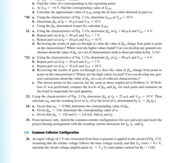
Transcribed Image Text:b. Find the value of a corresponding to this operating point.
c. At VCE = +6 V, find the corresponding value of ICEo-
d. Calculate the approximate value of ICBO using the de beta value obtained in part (a).
*20. a. Using the characteristics of Fig. 3.13a, determine IcEO at VcE = 10 V.
b. Determine Bac at Ig = 10 µA and VcE = 10 V.
c. Using the Bac determined in part (b), calculate IcBo-
21. a. Using the characteristics of Fig. 3.13a, determine Bg, at lg = 60 µA and Vcg = 4 V.
b. Repeat part (a) at Ig = 30 µA and VcE = 7 V.
c. Repeat part (a) at Ig = 10 µA and VcE = 10 V.
d. Reviewing the results of parts (a) through (c), does the value of Bg. change from point to point
on the characteristics? Where were the higher values found? Can you develop any general con-
clusions about the value of Ba: on a set of characteristics such as those provided in Fig. 3.13a?
*22. a. Using the characteristics of Fig. 3.13a, determine Byc at Ig = 60 µA and VcE = 4 V.
b. Repeat part (a) at Ig = 30 µA and VcE =7 V.
c. Repeat part (a) at Ig = 10 µA and VCE = 10 V.
d. Reviewing the results of parts (a) through (c), does the value of Bac change from point to
point on the characteristics? Where are the high values located? Can you develop any gen-
eral conclusions about the value of Bac On a set of collector characteristics?
e. The chosen points in this exercise are the same as those employed in Problem 21. If Prob-
lem 21 was performed, compare the levels of Bac and Bac for each point and comment on
the trend in magnitude for each quantity.
23. Using the characteristics of Fig. 3.13a, determine Ba, at Ig = 25 µA and VcE = 10 V. Then
calculate ag and the resulting level of Ig. (Use the level of Ic determined by Ic = Bap.)
24. a. Given that ase = 0.980, determine the corresponding value of Bac-
b. Given Bac = 120, determine the corresponding value of a.
c. Given that Bác = 120 and Ic = 2.0 mA, find Ig and Ig.
25. From memory only, sketch the common-emitter configuration (for npn and pnp) and insert the
proper biasing arrangement with the resulting current directions for Ig. Ic, and Ig.
3.6 Common-Collector Configuration
26. An input voltage of 2 V rms (measured from base to ground) is applied to the circuit of Fig. 3.21.
Assuming that the emitter voltage follows the base voltage exactly and that Ve (rms) = 0.1 V,
calculate the circuit voltage amplification (A, = V,/V) and emitter current for Rg = 1 kN.
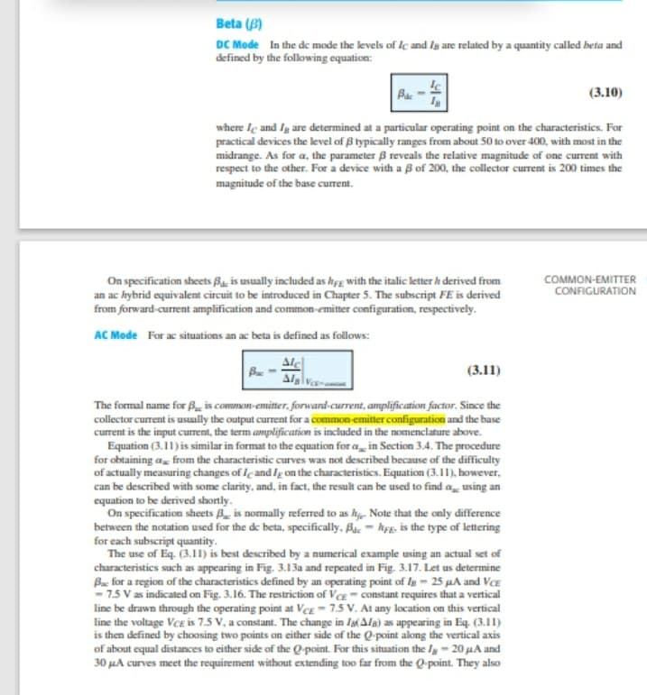
Transcribed Image Text:Beta (B)
DC Mode In the de mode the levels of lc and Ig are related by a quantity called beta and
defined by the following equation:
Ba
(3.10)
where Ie and Ig are determined at a particular operating point on the characteristics. For
practical devices the level of B typically ranges from about 50 to over 400, with most in the
midrange. As for a, the parameter B reveals the relative magnitude of one current with
respect to the other. For a device with a ß of 200, the collector current is 200 times the
magnitude of the base current.
On specification sheets Ba, is usually included as hsg with the italic letter h derived from
an ac hybrid equivalent circuit to be introduced in Chapter 5. The subscript FE is derived
from forward-current amplification and common-emitter configuration, respectively.
COMMON-EMITTER
CONFIGURATION
AC Mode For ac situations an ac beta is defined as follows:
Alc
(3.11)
The formal name for B, is common-emitter,. forwand-current, amplification factor. Since the
collector current is usually the output current for a common emitter configuration and the base
current is the input curent, the term amplification is included in the nomenclature above.
Equation (3.11) is similar in format to the cquation for a in Section 3.4. The procedure
for obtaining a, from the characteristic curves was not described because of the difficulty
of actually measuring changes of Icand Ig on the characteristics. Equation (3.11), bowever,
can be described with some clarity, and, in fact, the result can be used to find a, using an
equation to be derived shortly.
On specification sheets B_ is nomally referred to as hy, Note that the only difference
between the notation used for the de beta, specifically, Bue - hyɛ, is the type of lettering
for each subscript quantity.
The use of Eq. (3.11) is best described by a numerical example using an actual set of
characteristics such as appearing in Fig. 3.13a and repeated in Fig. 3.17. Let us determine
B for a region of the characteristics defined by an operating point of Ig - 25 µA and VCE
- 7.5 V as indicated on Fig. 3.16. The restriction of VcE- constant requires that a vertical
line be drawn through the operating point at Vcg- 7.5 V. At any location on this vertical
line the voltage Vee is 7.5 V, a constant. The change in Ia(Ala) as appearing in Eq. (3.II)
is then defined by choosing two points on cither side of the Q-point aklong the vertical axis
of about equal distances to either side of the Q-point. For this situation the Ig- 20 µA and
30 µA curves meet the requirement without extending too far from the Q-point. They also
Expert Solution
This question has been solved!
Explore an expertly crafted, step-by-step solution for a thorough understanding of key concepts.

This is a popular solution!

Trending now
This is a popular solution!

Step by step
Solved in 2 steps with 1 images

Knowledge Booster


Learn more about
Need a deep-dive on the concept behind this application? Look no further. Learn more about this topic, electrical-engineering and related others by exploring similar questions and additional content below.Recommended textbooks for you
Introductory Circuit Analysis (13th Edition)
Electrical Engineering
ISBN:
9780133923605
Author:
Robert L. Boylestad
Publisher:
PEARSON

Delmar's Standard Textbook Of Electricity
Electrical Engineering
ISBN:
9781337900348
Author:
Stephen L. Herman
Publisher:
Cengage Learning

Programmable Logic Controllers
Electrical Engineering
ISBN:
9780073373843
Author:
Frank D. Petruzella
Publisher:
McGraw-Hill Education
Introductory Circuit Analysis (13th Edition)
Electrical Engineering
ISBN:
9780133923605
Author:
Robert L. Boylestad
Publisher:
PEARSON
Delmar's Standard Textbook Of Electricity
Electrical Engineering
ISBN:
9781337900348
Author:
Stephen L. Herman
Publisher:
Cengage Learning
Programmable Logic Controllers
Electrical Engineering
ISBN:
9780073373843
Author:
Frank D. Petruzella
Publisher:
McGraw-Hill Education

Fundamentals of Electric Circuits
Electrical Engineering
ISBN:
9780078028229
Author:
Charles K Alexander, Matthew Sadiku
Publisher:
McGraw-Hill Education

Electric Circuits. (11th Edition)
Electrical Engineering
ISBN:
9780134746968
Author:
James W. Nilsson, Susan Riedel
Publisher:
PEARSON

Engineering Electromagnetics
Electrical Engineering
ISBN:
9780078028151
Author:
Hayt, William H. (william Hart), Jr, BUCK, John A.
Publisher:
Mcgraw-hill Education,