
Introductory Circuit Analysis (13th Edition)
13th Edition
ISBN: 9780133923605
Author: Robert L. Boylestad
Publisher: PEARSON
expand_more
expand_more
format_list_bulleted
Related questions
Question

Transcribed Image Text:1.
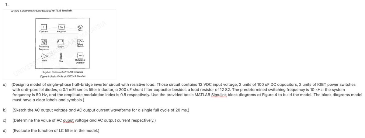
(Figure 4 illustrates the basic blocks of MATLAB Simulink).
b)
1/
Integrator
34
Scope
Mux
Sum
E
Switch
Relational
Operator
ABAN SAAN MALAYSIA
UNIVERS ABAN
Rajah 4: Blok asas MATLAB Simulink
Figure 4: Basic blocks of MATLAB Simulink
a) (Design a model of single-phase half-bridge inverter circuit with resistive load. Those circuit contains 12 VDC input voltage, 2 units of 100 uF DC capacitors, 2 units of IGBT power switches
with anti-parallel diodes, a 0.1 mEl series filter inductor, a 200 uF shunt filter capacitor besides a load resistor of 12 S2. The predetermined switching frequency is 10 kHz, the system
frequency is 50 Hz, and the amplitude modulation index is 0.8 respectively. Use the provided basic MATLAB Simulink block diagrams at Figure 4 to build the model. The block diagrams model
must have a clear labels and symbols.)
(Sketch the AC output voltage and AC output current waveforms for a single full cycle of 20 ms.)
c)
(Determine the value of AC ouput voltage and AC output current respectively.)
d) (Evaluate the function of LC filter in the model.)
SAVE
AI-Generated Solution
info
AI-generated content may present inaccurate or offensive content that does not represent bartleby’s views.
Unlock instant AI solutions
Tap the button
to generate a solution
to generate a solution
Click the button to generate
a solution
a solution
Knowledge Booster

Similar questions
- A three phase inverter below has a Y- connected load. The inverter frequency is fo = 60 Hz and the DC input voltage Vs = 220V. The applied control signal is a 180 deg conduction mode. The RMS Line to Line voltage Vo is equal to 179.63V. The total harmonic distortion (THD) is equal to: Select one: a. 48.34% b. 31.08% c. None of these d. 100%arrow_forwardSimulation is NOT required. Please show calculations please. Thank you.arrow_forward
Recommended textbooks for you
- Introductory Circuit Analysis (13th Edition)Electrical EngineeringISBN:9780133923605Author:Robert L. BoylestadPublisher:PEARSON
 Delmar's Standard Textbook Of ElectricityElectrical EngineeringISBN:9781337900348Author:Stephen L. HermanPublisher:Cengage Learning
 Programmable Logic ControllersElectrical EngineeringISBN:9780073373843Author:Frank D. PetruzellaPublisher:McGraw-Hill Education
  Fundamentals of Electric CircuitsElectrical EngineeringISBN:9780078028229Author:Charles K Alexander, Matthew SadikuPublisher:McGraw-Hill Education
 Electric Circuits. (11th Edition)Electrical EngineeringISBN:9780134746968Author:James W. Nilsson, Susan RiedelPublisher:PEARSON
 Engineering ElectromagneticsElectrical EngineeringISBN:9780078028151Author:Hayt, William H. (william Hart), Jr, BUCK, John A.Publisher:Mcgraw-hill Education,
Introductory Circuit Analysis (13th Edition)
Electrical Engineering
ISBN:9780133923605
Author:Robert L. Boylestad
Publisher:PEARSON
Delmar's Standard Textbook Of Electricity
Electrical Engineering
ISBN:9781337900348
Author:Stephen L. Herman
Publisher:Cengage Learning
Programmable Logic Controllers
Electrical Engineering
ISBN:9780073373843
Author:Frank D. Petruzella
Publisher:McGraw-Hill Education
Fundamentals of Electric Circuits
Electrical Engineering
ISBN:9780078028229
Author:Charles K Alexander, Matthew Sadiku
Publisher:McGraw-Hill Education
Electric Circuits. (11th Edition)
Electrical Engineering
ISBN:9780134746968
Author:James W. Nilsson, Susan Riedel
Publisher:PEARSON
Engineering Electromagnetics
Electrical Engineering
ISBN:9780078028151
Author:Hayt, William H. (william Hart), Jr, BUCK, John A.
Publisher:Mcgraw-hill Education,