
Tutorials in Introductory Physics
1st Edition
ISBN: 9780130970695
Author: Peter S. Shaffer, Lillian C. McDermott
Publisher: Addison Wesley
expand_more
expand_more
format_list_bulleted
Videos
Textbook Question
thumb_up100%
Chapter 6.1, Problem 1aT
Obtain a battery, a light bulb, and a single piece of wire. Connect these in a variety of ways.
Sketch each arrangement below.
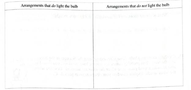
You should have found at least four different arrangements that light the bulb. How are these arrangements similar? How do they differ from arrangements in which the bulb does not light?
State the requirements that must be met in order for the bulb to light.
Expert Solution & Answer

Learn your wayIncludes step-by-step video

schedule02:25
Students have asked these similar questions
Two resistors with values of 44 Ω and 52 Ω are in parallel. This combination is connected in series with a 10 Ω resistor. The total potential is 120 V.
a) What is the equivalent resistance?
b) What is the current through each resistor?
c) What is the power through each resistor?
Remember to include the following when answering these questions:
What did you get? (your answer with the correct units and supporting work)
How did you get that? (the equation you chose to use to get your answer)
Why did you use that? (the concept that supports the use of the equation that you chose to use)
Three resistors of 25 Ω, 30 Ω and an unknown resistance R are connected in parallel and thecombination is connected to a 16 V source. If the total current delivered by the source is 1.5 A,determine the following:A. The value of R.B. The current in each resistor.C. Which resistor dissipates the highest power? Show your solution. Based on your answer,what conclusion can be made?
State which of the following statements are true and which are false. Give reasons for your
answers.
a) A very simple circuit consists of a battery connected across a resistor. In this circuit, the
battery and the resistor are both in series and also in parallel.
b) A resistor R and a capacitor C connected in series combine as = +
1
1
RC
R
c) Natural uranium is not radioactive until it has been processed by enrichment for use in
fission reactors or bombs.
d) Infrared light is more likely to cause electrons to be emitted from a metal than ultraviolet
light.
e) Special and General Relativity effects both matter for the operation of GPS, the former slow-
ing down the clocks on GPS satellites relative to clocks on Earth and the latter speeding
them up.
Chapter 6 Solutions
Tutorials in Introductory Physics
Ch. 6.1 - Obtain a battery, a light bulb, and a single piece...Ch. 6.1 - A student has briefly connected a wire across the...Ch. 6.1 - Light a bulb using a battery and a single wire....Ch. 6.1 - Carefully examine a bulb. Two wires extend from...Ch. 6.1 - Compare the brightness of the two bulb with each...Ch. 6.1 - Compare the brightness of each of the bulbs in the...Ch. 6.1 - We may think of a bulb as percentage an obstacle,...Ch. 6.1 - Compare the brightness of the bulbs in this...Ch. 6.1 - Is the brightness of each bulb in the two-bulb...Ch. 6.1 - Formulate a rule for predicting how the current...
Ch. 6.1 - Does the amount of current through a battery seem...Ch. 6.1 - Unscrew one of the bulbs in the two-bulb parallel...Ch. 6.1 - The circuit at tight contains three identical...Ch. 6.1 - Show that a simple application of the model for...Ch. 6.2 - The circuits at right contain identical batteries,...Ch. 6.2 - The circuits at right contain identical batteries...Ch. 6.2 - Predict the relative brightness of bulbs...Ch. 6.2 - Set up the circuit with a single bulb and the...Ch. 6.2 - Set up the circuit containing two bulbs in series...Ch. 6.2 - Predict what the voltmeter would read if it were...Ch. 6.2 - Set up the circuit with two bulbs in parallel as...Ch. 6.2 - Answer the following questions based on the...Ch. 6.2 - Set up the circuit with three bulbs as shown and...Ch. 6.2 - Before setting up the circuit shown at right:...Ch. 6.2 - Both circuits al right have more than one path for...Ch. 6.3 - A capacitor is connected to a battery, bulb, and...Ch. 6.3 - Remove the capacitor and the bulb from the...Ch. 6.3 - Suppose an uncharged capacitor is connected in...Ch. 6.3 - Suppose that instead of connecting the uncharged...Ch. 6.3 - Suppose that the bulbs were connected in parallel...Ch. 6.3 - After completing the experiments above, two...Ch. 6.3 - Suppose that a different capacitor of smaller...Ch. 6.3 - Before connecting the circuit a student makes the...Ch. 6.3 - Make the following prediction on the basis of your...
Additional Science Textbook Solutions
Find more solutions based on key concepts
2. True or false? Equal masses of two different gases placed in containers of equal volume at equal temperature...
College Physics (10th Edition)
77. What colors of ink do color ink-jet printers use to produce a full range of colors? Do the colors form by c...
Conceptual Physical Science (6th Edition)
Bacterial Evolution. Suppose that a mutation occurs in about 1 out of every 1 million bacterial cells, and supp...
Life in the Universe (4th Edition)
BIO THE SPINNING EEL. American eels (Anguilla rostrata) are freshwater fish with long, slender bodies that we c...
University Physics (14th Edition)
Knowledge Booster


Learn more about
Need a deep-dive on the concept behind this application? Look no further. Learn more about this topic, physics and related others by exploring similar questions and additional content below.Similar questions
- In the circuit shown in (Figure 1) the batteries have negligible internal resistance and the meters are both idealized. With the switch S open, the voltmeter reads 18.0 V. Part A For related problemsolving tips and strategies, you may want to view a Video Tutor Solution of A complex network. Find the emf Ɛ of the battery. Express your answer in volts. E = V Submit Request Answer igure 1 of 1 Part B What will the ammeter read when the switch is closed? EFE 30.0 N Express your answer in amperes. 20.0 75.02 Ω 25.0 V 50.0 Ω Ω ΑΣφ E=? S I = A Submit Request Answerarrow_forwardYou may want to review (Pages 768 - 771). Part A What is the magnitude of the current in the 13 S2 resistor in (Figure 1)? Express your answer with the appropriate units. HA ? I= 0.23 A Submit Previous Answers Request Answer X Incorrect; Try Again; 2 attempts remaining Part B What is the direction of the current in the 13 $2 resistor in (Figure 1)? from left to right through the resistor from right to left through the resistor Figurearrow_forwardConsider the following circuit ww R1 R2 where V = 10.0V, R2= 10.0k2 and R3 = 20.0kN. 1. Are the resistors connected in series or parallel? 2. What is the equivalent resistance of the resistor pair. 3. Use V = IR and the equivalent resistance to find the total current though the battery. 4. How much current flows through each of the two original resistors? (Hint: Note that each of the two resistors has the same voltage across them so you can use ohms law for each of them.) 5. Sum the two currents together, do you get the current through the battery? wwarrow_forward
- Three 100 Ohm resistors are connected as shown in the figure. The maximum power that can be safely delivered to any of the resistors is 25.0 W. A. What is the maximum potential difference that can be applied to terminals a and b? B. For the voltage determined in part (a), what is the power delivered to each resistor? C. What is the total power delivered to the resistor combination? D. Exercise 6: Consider the circuit shown in the figure. Determine (a) the current in the 20 Ohm resistor and E. The potential difference between points a and b.arrow_forwardIn the circuit shown in the figure (Figure 1), the curent in the 20.0-V battery is 5.00 A in the direction shown and the voltage across the 8.00-S2 resistor is 18.0 V. with the lower end of the resistor at higher potential. Part A Find the emf of the battery X. ? E = V Request Answer Submit Figure 1 of 1 Part B Find the polarity of the battery X. 20.0 N ww- 30.0 N ww R R ww the upper terminal + the upper terminal - 18.0 N {8.00 N 200.0 V Request Answer Submit 20.0 V 5.00 A Part C Find the current I through the 200.0-V battery.arrow_forwardConsider the circuit shown in the figure(Figure 1). Suppose the four resistors in this circuit have the values R₁ = 13, R₂ = 6.4, R3 = 7.6 S2, and R4 = 14 S2, and that the emf of the battery is & = 18 V. Figure C E R₁ ww B ww 1 of 1 ww R₂ RA ww Aarrow_forward
- Review I Constants ▼ Part A For the circuit shown in the figure(Figure 1) find the current through each resistor. Express your answers using two significant figures. Enter your answers numerically separated by commas. I2 n, I4 n, I6 n, I12 n, Is n = A %3D Submit Request Answer Part B For the circuit shown in the figure find the potential difference across each resistor. Express your answers using two significant figures. Enter your answers numerically separated by commas. Figure 1 of 1 ΑΣφ ? AV2 n, AV4 2, AV6 2, AV12 o, AV3 n = V Submit Request Answer 24 VE 6 0 12 N Provide Feedback Next > warrow_forwardConsider the following circuit R1 V R2 where V = 30V, R2 = 30 and R = 30. 1. Are the resistors connected in series or parallel? 2. What is the equivalent resistance of the resistor pair. 3. Use V = IR and the equivalent resistance to find the total current though the battery. %3D 4. How much current flows through each of the two original resistors? wwarrow_forwardThe terminals of a 0.70 V watch battery are connected by a 60.0-m-long gold wire with a diameter of 0.100 mm. You may want to review (Pages 755 - 759). For general problem-solving tips and strategies for this topic, you may want to view a Video Tutor Solution of Soil resistivity. Part A What is the current in the wire? Express your answer using three significant figures. VE ΑΣΦ I = 8.45 Submit Previous Answers Request Answer X Incorrect; Try Again ? mAarrow_forward
- Take three resistors.R1=25 ohms, R2=17 ohms and R3 = 3 ohms. Let V0 = 30 V. Now, connect the resistors as shown in the figure, and connect them to the power supply. Record the voltage across each resistor, using the voltmeter. a. Are the voltages V1, V2 and V3 equal to each other? Why or why not? b. Calculate the total voltage V = V1 + V2 + V3. Explain why it has the value it does. c. Use Ohm’s law to calculate the current through each resistor. d. Calculate the effective resistance of the circuit. e. Construct another circuit by replacing the 3 resistors with the single effective resistance. please solve all points..arrow_forwardA schematic diagram of an electrical circuit is shown consisting of three resistors and one voltage source (battery). Calculate the current in amps through R2. V = 16 V, R1= 125 N, R2= 70 2, R3= 70 N %3D Enter numeric answer only. No other symbols. Example: 1.85 R1 R2 + V R3 Type your answer. Next Lenovo Home End Insert Delete F6 F7 F8 F9 F10 F11 F12arrow_forwardA. Notice that the switches (indicated by positions A and B) are set to position A, and the capacitors and two identical lightbulbs (labeled LB1 and LB2) are not connected. Calculate the equivalent resistance of the circuit and the total current. B. How much current flows through the 5 Ω resistor? How about the 3 Ω resistor? C. How much power is dissipated by each of the resistors? D. Now suppose the switches are both changed to position B, such that the capacitors and the identical light bulbs are connected. Which light bulb will turn off first? Explain.Hint: consider that the resistances of LB1 and LB2 are identical. E. How much charge will each of the capacitors have in the end?arrow_forward
arrow_back_ios
SEE MORE QUESTIONS
arrow_forward_ios
Recommended textbooks for you
 College PhysicsPhysicsISBN:9781305952300Author:Raymond A. Serway, Chris VuillePublisher:Cengage Learning
 University Physics (14th Edition)PhysicsISBN:9780133969290Author:Hugh D. Young, Roger A. FreedmanPublisher:PEARSON
 Introduction To Quantum MechanicsPhysicsISBN:9781107189638Author:Griffiths, David J., Schroeter, Darrell F.Publisher:Cambridge University Press
 Physics for Scientists and EngineersPhysicsISBN:9781337553278Author:Raymond A. Serway, John W. JewettPublisher:Cengage Learning
 Lecture- Tutorials for Introductory AstronomyPhysicsISBN:9780321820464Author:Edward E. Prather, Tim P. Slater, Jeff P. Adams, Gina BrissendenPublisher:Addison-Wesley
 College Physics: A Strategic Approach (4th Editio...PhysicsISBN:9780134609034Author:Randall D. Knight (Professor Emeritus), Brian Jones, Stuart FieldPublisher:PEARSON
College Physics
Physics
ISBN:9781305952300
Author:Raymond A. Serway, Chris Vuille
Publisher:Cengage Learning
University Physics (14th Edition)
Physics
ISBN:9780133969290
Author:Hugh D. Young, Roger A. Freedman
Publisher:PEARSON
Introduction To Quantum Mechanics
Physics
ISBN:9781107189638
Author:Griffiths, David J., Schroeter, Darrell F.
Publisher:Cambridge University Press
Physics for Scientists and Engineers
Physics
ISBN:9781337553278
Author:Raymond A. Serway, John W. Jewett
Publisher:Cengage Learning
Lecture- Tutorials for Introductory Astronomy
Physics
ISBN:9780321820464
Author:Edward E. Prather, Tim P. Slater, Jeff P. Adams, Gina Brissenden
Publisher:Addison-Wesley
College Physics: A Strategic Approach (4th Editio...
Physics
ISBN:9780134609034
Author:Randall D. Knight (Professor Emeritus), Brian Jones, Stuart Field
Publisher:PEARSON
How To Solve Any Resistors In Series and Parallel Combination Circuit Problems in Physics; Author: The Organic Chemistry Tutor;https://www.youtube.com/watch?v=eFlJy0cPbsY;License: Standard YouTube License, CC-BY