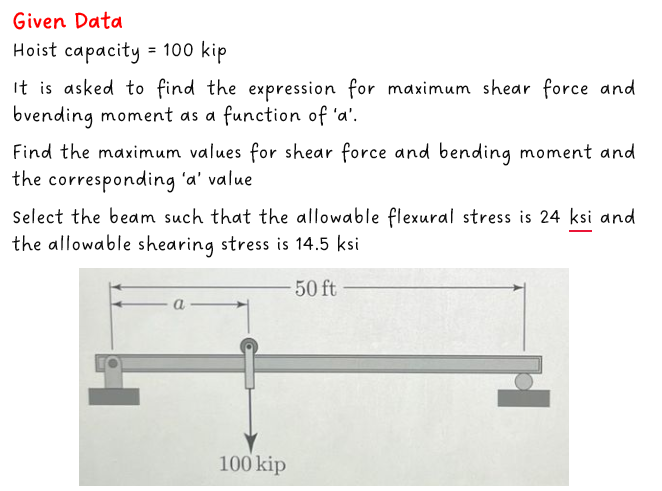
A Gantry crane is a crane that lifts objects by a hoist, which is fitted in a hoist trolley than can move horizontally on a beam. In the example shown below, the capacity of the hoist is 100 kip and the beam is simply supported with a span of 50 ft. (a) The shear force and bending moment distributions vary with the position a of the hoist trolley. Using shear force and bending moment diagrams, determine expressions for the maximum shear force Vmax and bending moment Mmax as functions of a for 0 < a < 25 ft. (b) Determine the values of a that maximize Vmax and Mmax, and determine these maximum values. (c) Select the lightest permissible wide-flange beam to support the hoist, if the al- lowable flexural stress is 24 ksi and the allowable shearing stress is 14.5 ksi. -50 ft 100 kip
A Gantry crane is a crane that lifts objects by a hoist, which is fitted in a hoist trolley than can move horizontally on a beam. In the example shown below, the capacity of the hoist is 100 kip and the beam is simply supported with a span of 50 ft. (a) The shear force and bending moment distributions vary with the position a of the hoist trolley. Using shear force and bending moment diagrams, determine expressions for the maximum shear force Vmax and bending moment Mmax as functions of a for 0 < a < 25 ft. (b) Determine the values of a that maximize Vmax and Mmax, and determine these maximum values. (c) Select the lightest permissible wide-flange beam to support the hoist, if the al- lowable flexural stress is 24 ksi and the allowable shearing stress is 14.5 ksi. -50 ft 100 kip

Elements Of Electromagnetics
7th Edition
ISBN:9780190698614
Author:Sadiku, Matthew N. O.
Publisher:Sadiku, Matthew N. O.
ChapterMA: Math Assessment
Section: Chapter Questions
Problem 1.1MA

Related questions

Question

Transcribed Image Text:. A Gantry crane is a crane that lifts objects by a hoist, which is fitted in a hoist trolley
than can move horizontally on a beam. In the example shown below, the capacity of
the hoist is 100 kip and the beam is simply supported with a span of 50 ft.
(a) The shear force and bending moment distributions vary with the position a of
the hoist trolley. Using shear force and bending moment diagrams, determine
expressions for the maximum shear force Vmax and bending moment Mmax as
functions of a for 0 < a < 25 ft.
(b) Determine the values of a that maximize Vmax and Mmax, and determine these
maximum values.
(c) Select the lightest permissible wide-flange beam to support the hoist, if the al-
lowable flexural stress is 24 ksi and the allowable shearing stress is 14.5 ksi.
50 ft
a
100 kip

Transcribed Image Text:TABLE A-1 Wide-Flange Beams (U.S. Customary Units)
FLANGE
Desig
nation
W36 X 230
X 160
W33 X 201
x 152
X 130
W30 X 132
X 108
W27 X 146
X 94
W24 X 104
X 84
X 62
W21 x 101
X 83
X 62
W18 X 97
X 76
X 60
W16 X 100
X 67
X 40
x 26
W14 X 120
X 82
X 43
X 30
W12 X 96
X 65
x 50
X 30
W10 X 60
X 45
X 30
X 22
W8 X 40
X 31
X 24
X 15
W6 X 25
X 16
W5 X 16
W4 X 13
Area
(10²)
67.6
47.0
59.1
44.7
38.3
38.9
31.7
42.9
27.7
30.6
24.7
18.2
29.8
24.3
18.3
28.5
22.3
17.6
29.4
19.7
11.8
7.68
35.3
24.1
12.6
8.85
28.2
19.1
14.7
8.79
17.6
13.3
8.84
6.49
11,7
9.13
7.08
4.44
7.34
4.74
4.68
3.83
Depth
(in.)
35.90
36.01
H
33.68
33.49
33.09
30.31
29.83
27.38
26.92
24.06
24.10
23.74
21.36
21.43
20.99
18.59
1821
18.24
16,97
16.33
16.01
15.69
14.48
14.31
13.66
13.84
12.71
12.12
12.19
12.34
10.22
10.10
10.47
10.17
8.25
8.00
7.93
8.11
6.38
6.28
5.01
4.16
for
Width
(in.)
16.470
12.000
15.745
11.565
11.510
10.545
10.475
13.965
9.990
12.750
9.020
7,040
12.290
8.355
8.240
11.145
11.035
7.555
10.425
10.235
6.995
5.500
14.670
10.130
7.995
6.730
12.160
12.000
8.080
6.520
10.080
8.020
5.810
5.750
8.070
7.995
6.495
4.015
6.080
4.030
5.000
4.060
Thick-
ness
(in.)
1.260
1.020
1.150
1.055
0.855
1.000
0.760
0.975
0.745
0.750
0.770
0.590
0.800
0.835
0.615
0.870
0.680
0.695
0.985
0.665
0.505
0.345
0.940
0.855
0.530
0.385
0.900
0.605
0.640
0.440
0.680
0.620
0.510
0.360
0.560
0.435
0.400
0.315
0.455
0.405
0.360
0.345
Web
Thick-
ness
(in.)
0.760
0.650
0.715
0.635
0.580
0.615
0.545
0.605
0.490
0.500
0.470
0.430
0.500
0.515
0.400
0.535
0.425
0.415
0.585
0.395
0.305
0.250
0.590
0.510
0.305
0.270
0.550
0.390
0.370
0.260
0.420
0.350
0.300
0.240
0.360
0.285
0.245
0.245
0.320
0.260
0.240
0.280
I
(in*)
15000
9750
11500
8160
6710
5770
4470
5630
3270
3100
2370
1550
2420
1830
1330
1750
1330
984
1490
954
518
301
1380
882
428
291
833
$33
394
238
341
248
170
118
146
110
82.8
48.0
53.4
32.1
21.3
11.3
AXTS X-X
S
(in³)
837
542
684
487
406
380
299
411
243
258
196
131
227
171
127
188
146
108
175
117
64.7
38.4
190
123
62.7
42.0
131
87.9
64.7
38.6
66.7
49.1
32.4
23.2
35.5
27.5
20.9
11.8
16.7
10.2
8.51
5.46
H
X-X'
(in)
14.9
14.4.
14.0
13.5
13.2
12.2
11.9
Y
11.4
10.9
10.1
9.79
9.23
9.02
8.67
8.54
7.82
7.73
7.47
7.10
6.96
6.63
6.26
6.24
6.05
5.82
5.73
5.44
5.28
5.18
5.21
4.39
4.33
4.38
4.27
3.53
3.47
3.42
3.29
2.70
2.60
2.13
1.72
Courtesy of the American Institute of Steel Construction.
*W means wide-flange beam, followed by the nominal dopth in inches, then the weight in pounds per foot of length.
I
(in¹)
940
295
749
273
218
196
146
443
124
259
94.4
34.5
248
81.4
57.5
201
152
50.1
186
119
28.9
9.59
495
148
45.2
19.6
270
174
56.3
20.3
116
$3.4
16.7
11.4
49.1
37.1
18.3
3.41
17.1
4.43
7.51
3.86
AXIS Y-Y
S
(in³)
114
49.1
95.2
47.2
37.9
37.2
27.9
63.5
24.8
40.7
20.9
9.80
40.3
19.5
13.9
36.1
27.6
13.3
35.7
23.2
8.25
3.49
67.5
29.3
11.3
5.82
44.4
29.1
13.9
6.24
23.0
13.3
5.75
3.97
12.2
9.27
5.63
1.70
5.61
2.20
3.00
1.90
3.73
2.50
3.56
2.47
2.39
2.25
2.15
3.21
2.12
2.91
1.95
1.38
2.89
1.83
1.77
2.65
2.61
1.69
2.52
2.46
1.57
1.12
3.74
2.48
1.89
1.49
3.09
3.02
1.96
1.52
2.57
2.01
1.37
1.33
2.04
2.02
1.61
0.876
1.52
0.967
1.27
1.00
Expert Solution
Step 1

Trending now
This is a popular solution!

Step by step
Solved in 2 steps with 5 images

Knowledge Booster


Learn more about
Need a deep-dive on the concept behind this application? Look no further. Learn more about this topic, mechanical-engineering and related others by exploring similar questions and additional content below.Recommended textbooks for you
Elements Of Electromagnetics
Mechanical Engineering
ISBN:
9780190698614
Author:
Sadiku, Matthew N. O.
Publisher:
Oxford University Press

Mechanics of Materials (10th Edition)
Mechanical Engineering
ISBN:
9780134319650
Author:
Russell C. Hibbeler
Publisher:
PEARSON

Thermodynamics: An Engineering Approach
Mechanical Engineering
ISBN:
9781259822674
Author:
Yunus A. Cengel Dr., Michael A. Boles
Publisher:
McGraw-Hill Education
Elements Of Electromagnetics
Mechanical Engineering
ISBN:
9780190698614
Author:
Sadiku, Matthew N. O.
Publisher:
Oxford University Press
Mechanics of Materials (10th Edition)
Mechanical Engineering
ISBN:
9780134319650
Author:
Russell C. Hibbeler
Publisher:
PEARSON
Thermodynamics: An Engineering Approach
Mechanical Engineering
ISBN:
9781259822674
Author:
Yunus A. Cengel Dr., Michael A. Boles
Publisher:
McGraw-Hill Education

Control Systems Engineering
Mechanical Engineering
ISBN:
9781118170519
Author:
Norman S. Nise
Publisher:
WILEY

Mechanics of Materials (MindTap Course List)
Mechanical Engineering
ISBN:
9781337093347
Author:
Barry J. Goodno, James M. Gere
Publisher:
Cengage Learning

Engineering Mechanics: Statics
Mechanical Engineering
ISBN:
9781118807330
Author:
James L. Meriam, L. G. Kraige, J. N. Bolton
Publisher:
WILEY