Engineering Mechanics: Dynamics (14th Edition)
14th Edition
ISBN: 9780133915389
Author: Russell C. Hibbeler
Publisher: PEARSON
expand_more
expand_more
format_list_bulleted
Concept explainers
Videos
Textbook Question
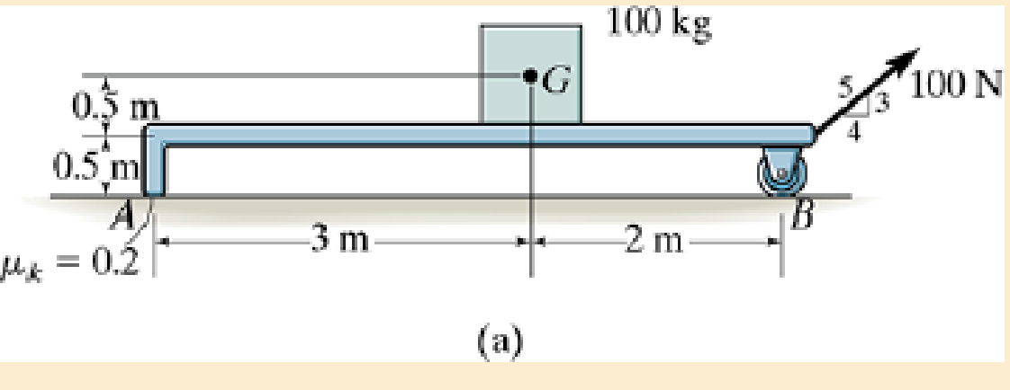
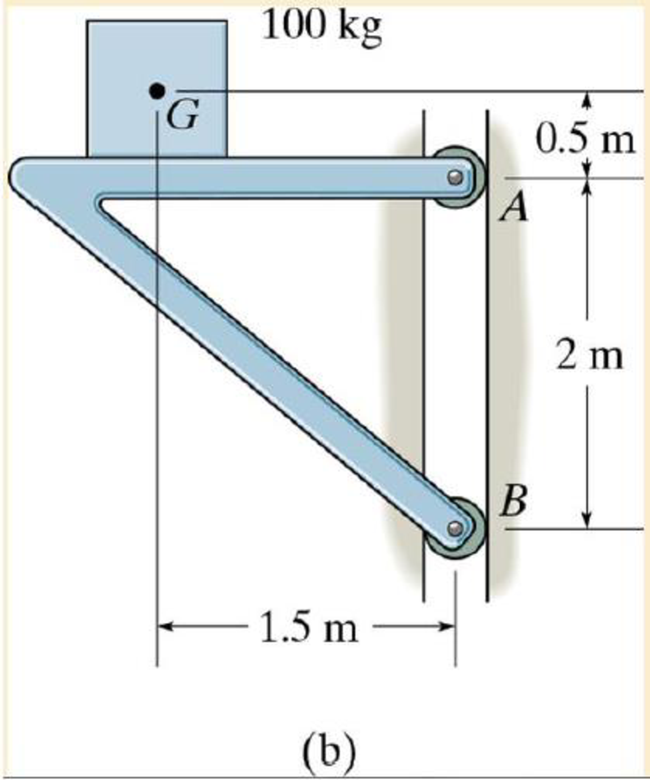
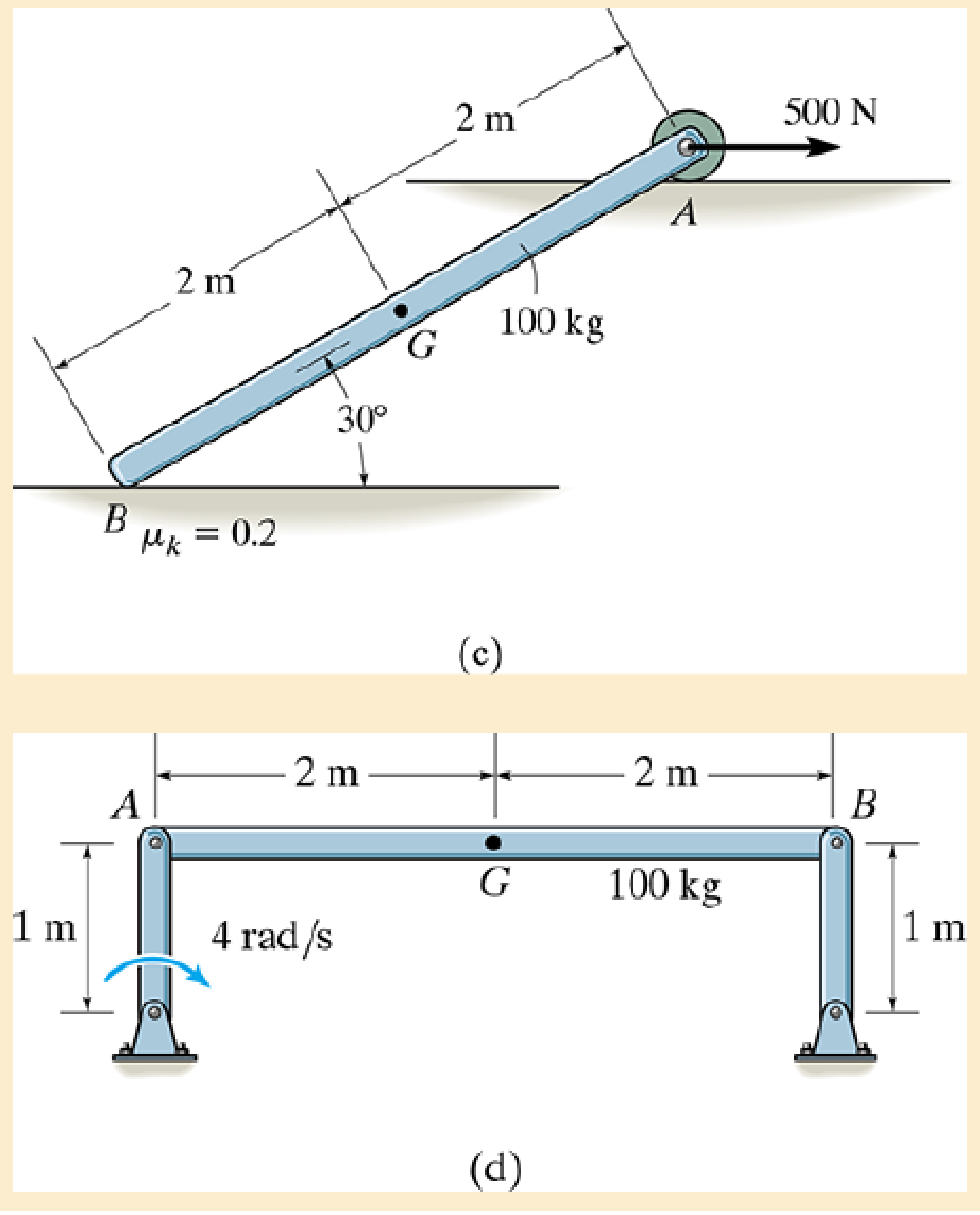
Chapter 17.3, Problem 1PP
Draw the free-body and kinetic diagrams of the object AB.
Expert Solution & Answer
Want to see the full answer?
Check out a sample textbook solution
Students have asked these similar questions
Assuming block B will slide to the right.
A.) Draw the Free body diagrams for the blocks separately (state a conservative force)
B.) Draw the kinematic diagrams for the block separately.
The 544g collar is free to slide on the smooth rod OA.
The rod rotates about pin O at constant angular velocity, é.
a =en + še, = a = RÔ?e, + RÖe, for a circular path, R = radius
2.1 Use N-T coordinates, draw a FBD and a kinetic diagram to determine
the minimum value of é for which the collar will maintain contact with the
stop at A throughout the rotation.
2.2 Would friction between the collar and the rod affect your result in 2.1?
1. The PASCO human arm model is configured such that
the cord representing the bicep is perfectly vertical and
the forearm is at 90° (in the figure to the right, the cord
is not quite vertical). A mass of 100 g is attached to the
hand. Draw a free-body diagram on the figure to the
right showing all forces which act on the forearm.
The force of the bicep F on the arm
The force of the humerus FH on the arm
The weight of the forearm W
The mass in the hand Wm
100 g
Be careful to draw the force vectors with tails beginning at the point where the force is actually
applied to the forearm.
2. Consider the free body diagram below. Determine the perpendicular component F̟ of the
force F exerted by the biceps brachii on the forearm. Use the fact that cos 0 = H/B to write
this component directly in terms of the humerus length H and the biceps length B.
H
3. If the forearm is in equilibrium, then there is no angular acceleration and therefore the sum of
the torques applied to the forearm must be…
Chapter 17 Solutions
Engineering Mechanics: Dynamics (14th Edition)
Ch. 17.1 - The rod's density end cross-sectional area. A are...Ch. 17.1 - Determine the mass of the cylinder end its moment...Ch. 17.1 - The nag has a mass m.Ch. 17.1 - Determine the radius of gyration kx. The density...Ch. 17.1 - The specific weight of the material is = 380...Ch. 17.1 - Determine the moment of inertia Iz and express the...Ch. 17.1 - Determine the moment of inertia Ix and express the...Ch. 17.1 - Defending the moment of inertia Iy and express the...Ch. 17.1 - Express the result in terms of the mass m of the...Ch. 17.1 - Determine me radius of gyration of the pendulum...
Ch. 17.1 - Determine the mass moment of inertia of the...Ch. 17.1 - Determine the moment of inertia of the solid steel...Ch. 17.1 - Determine the wheels moment of inertia about an...Ch. 17.1 - If the large ring, small ring and each of the...Ch. 17.1 - The thin plate has a hole in its center its...Ch. 17.1 - The material has a mass per unit area of 20 kg/m2.Ch. 17.1 - The block has a mass of 3 kg and the semicylinder...Ch. 17.1 - The block has a mass of 3 kg and the semicylinder...Ch. 17.1 - The material has a specific weight = 90 lb/ft3.Ch. 17.1 - Prob. 20PCh. 17.1 - Determine the location y of the center of mass G...Ch. 17.1 - The material is steel having a density of = 7.85...Ch. 17.1 - The material is steel having a density of = 7.85...Ch. 17.3 - Draw the free-body and kinetic diagrams of the...Ch. 17.3 - Draw the free-body and kinetic diagrams of the...Ch. 17.3 - Determine the acceleration of the can and the...Ch. 17.3 - If the 80-kg cabinet is allowed to roll down the...Ch. 17.3 - Determine the maximum acceleration of the frame...Ch. 17.3 - Also what is the corresponding normal reaction on...Ch. 17.3 - Determine the tension developed in the rods and...Ch. 17.3 - If it is subjected to a couple moment M = 450 N ...Ch. 17.3 - Determine how far the door moves in 25, starting...Ch. 17.3 - Determine the constant force F that must be...Ch. 17.3 - Initially at take-off the engines provide a thrust...Ch. 17.3 - If it starts from rest it causes the rear wheels...Ch. 17.3 - If the winch at B draws in the cable with an...Ch. 17.3 - Determine the greatest acceleration of the...Ch. 17.3 - Determine the internal axial, shear, and...Ch. 17.3 - If the coefficient of kinetic friction between the...Ch. 17.3 - Determine the reactions at both the wheels at A...Ch. 17.3 - Also, what is the acceleration of the cart? The...Ch. 17.3 - If it is subjected to a horizontal force of P =...Ch. 17.3 - Determine its initial acceleration if a man pushes...Ch. 17.3 - Determine the initial acceleration of a desk when...Ch. 17.3 - Determine the maximum force P that can be applied...Ch. 17.3 - Determine the maximum force P that can be applied...Ch. 17.3 - If it is released from rest, determine the...Ch. 17.3 - It is carried on a truck as shown. Determine the...Ch. 17.3 - It is carried on a truck as shown. If the truck...Ch. 17.3 - Determine the smallest acceleration that will...Ch. 17.3 - The coefficients of static and kinetic friction...Ch. 17.3 - If the collar is given a constant acceleration of...Ch. 17.3 - If it is supported by the cable AB and hinge at C,...Ch. 17.3 - If it is supported by the cable AB and hinge at C,...Ch. 17.3 - If the acceleration is a = 20 ft/s2, determine the...Ch. 17.3 - If h = 3 ft, determine the snowmobiles maximum...Ch. 17.3 - If the carts mass is 30 kg and it is subjected to...Ch. 17.3 - The uniform rod BC has a mass of 15 kg.Ch. 17.3 - If the acceleration of the truck is at = 0.5 m/s2,...Ch. 17.3 - If the angle = 30, determine the acceleration of...Ch. 17.3 - Determine the largest initial angular acceleration...Ch. 17.3 - Determine the initial friction and normal force of...Ch. 17.3 - Determine the largest initial angular acceleration...Ch. 17.3 - Determine the normal force NE, shear force VE, and...Ch. 17.4 - If the wheel starts from rest determine its...Ch. 17.4 - Determine the angular velocity of the disk when t...Ch. 17.4 - Determine the tangential and normal components of...Ch. 17.4 - Determine the tangential and normal components or...Ch. 17.4 - Determine the horizontal and vertical components...Ch. 17.4 - If the rod has a counterclockwise angular velocity...Ch. 17.4 - If the wheel is subjected to a moment M = (5t) N ...Ch. 17.4 - Determine its initial angular acceleration and the...Ch. 17.4 - If it is released from rest when = 0. determine...Ch. 17.4 - If it is released from rest in the position shown,...Ch. 17.4 - The reel rests on rollers at A and B and has a...Ch. 17.4 - The spring has a stiffness k = 5 lb ft/rad, so...Ch. 17.4 - The spring has a stiffness k = 5 lb ft/rad, so...Ch. 17.4 - If a force of F=(142)N, where is in radians, is...Ch. 17.4 - If no slipping occurs between them determine the...Ch. 17.4 - Show that IG may be eliminated by moving the...Ch. 17.4 - Treat the beam as a uniform slender rod.Ch. 17.4 - It consists of a 100-kg steel plate AC and a...Ch. 17.4 - It is pin supported at both ends by two brackets...Ch. 17.4 - It is pin supported at both ends by two brackets...Ch. 17.4 - Determine its angular velocity when t = 2 s...Ch. 17.4 - If it is placed on the ground for which the...Ch. 17.4 - Compute the time needed to unravel 5 m of cable...Ch. 17.4 - If the rotor always maintains a constant clockwise...Ch. 17.4 - It is originally spinning at = 40 rad/s. If it is...Ch. 17.4 - It is pin supported at both ends by two brackets...Ch. 17.4 - Disk E has a weight of 60 lb and is initially at...Ch. 17.4 - If the cylinders are released from rest, determine...Ch. 17.4 - If the pulley can be treated as a disk of mass 3...Ch. 17.4 - If the pulley can be treated as a disk of mass M,...Ch. 17.4 - Assume that the board is uniform and rigid, and...Ch. 17.4 - At the instant the rolor is horizontal it has an...Ch. 17.4 - Determine the initial tending moment at the fixed...Ch. 17.4 - Movement is controlled by the electromagnet E,...Ch. 17.4 - If it is rotating in the vertical plane at a...Ch. 17.4 - Determine the angular acceleration of the rod and...Ch. 17.4 - Determine the horizontal and vertical components...Ch. 17.4 - Determine the horizontal and vertical components...Ch. 17.5 - If the powder burns at a constant rate of 20 g/s...Ch. 17.5 - Determine the acceleration of the bars mass center...Ch. 17.5 - Determine the acceleration of its mass center and...Ch. 17.5 - When the wheel is subjected to the couple moment,...Ch. 17.5 - Determine the angular acceleration of the sphere...Ch. 17.5 - If the couple moment is applied to the spool and...Ch. 17.5 - If the rod is released from rest at = 0,...Ch. 17.5 - rolls without slipping, show that when moments are...Ch. 17.5 - If it is initially at rest and is subjected to a...Ch. 17.5 - The uniform 150-lb beam is initially at rest when...Ch. 17.5 - If the coefficients of static and kinetic friction...Ch. 17.5 - If the coefficients of static and kinetic friction...Ch. 17.5 - If the coefficients of static and kinetic friction...Ch. 17.5 - Solve Prob.17-96 if the cord and force P = 50 N...Ch. 17.5 - If the coefficients of static and kinetic friction...Ch. 17.5 - If a horizontal force of F = 80 N is applied to...Ch. 17.5 - If slipping does not occur, determine the rings...Ch. 17.5 - Neglect the thickness of the ring.Ch. 17.5 - Using a collar of negligible mass, its end A is...Ch. 17.5 - If the pin is connected to a track which is giver...Ch. 17.5 - Assume the roller to be a uniform cylinder and...Ch. 17.5 - Also, find the angular acceleration of the roller....Ch. 17.5 - Determine the bars initial angular acceleration...Ch. 17.5 - Solve Prob.17-106 if the roller is removed and the...Ch. 17.5 - If the coefficient of static friction at A is s, =...Ch. 17.5 - If the truck has an acceleration of 3 m/s2...Ch. 17.5 - A cord is wrapped around the periphery of the disk...Ch. 17.5 - If the coefficient of static friction at A is s =...Ch. 17.5 - At this instant the center of gravity of the...Ch. 17.5 - Determine the initial angular acceleration of the...Ch. 17.5 - Determine the time before it starts to roll...Ch. 17.5 - If they are released from rest determine the...Ch. 17.5 - Determine the normal force which the path exerts...Ch. 17.5 - If it is originally at rest while being supported...Ch. 17.5 - If the pin support at A suddenly fails, determine...Ch. 17.5 - Determine its angular acceleration.Ch. 17.5 - If the coefficient of kinetic friction between the...Ch. 17.5 - Determine the normal reactions at each of the...Ch. 17.5 - Determine the internal axial force Ex, shear force...Ch. 17.5 - Determine the maximum acceleration it can have if...Ch. 17.5 - The roil rest against a wall for which the...Ch. 17.5 - Determine the magnitude of force F and the initial...Ch. 17.5 - Compute the reaction at the pin O just after the...Ch. 17.5 - if the coefficient of kinetic friction at the...Ch. 17.5 - The coefficient of kinetic friction is A = 0.3.
Knowledge Booster


Learn more about
Need a deep-dive on the concept behind this application? Look no further. Learn more about this topic, mechanical-engineering and related others by exploring similar questions and additional content below.Similar questions
- Obtain the equation of motion by drawing the free body diagrams of the given system.arrow_forwardThe 300kn sphere is supported by a pull p and a 200kn weight passing over a frictionless pulley. If a=30°. Computer the value of p and tangent.arrow_forwardRECTILINEAR MOTION. Indicate free body diagram and complete solution.arrow_forward
- Derive the equation of motion for the following system, using (the rotation of the beam about the hinge) as the degree-of-freedom. Not that there is an applied force (Fo sin wt) as well as an applied moment (Mo sin wt). The total bar mass is m. Treat the bar as two bars: one to the left of the hinge point; one to the right. The one to the left has a mass moment of inertia of- mL²; the one to the 27 192 1 mL². Then transform this Fo sin cor right has a mass moment of inertia of- 192 differential equation of the Laplace domain, assuming zero initial conditions. Lastly, compute the damping ratio and damped natural frequency for this system. TET 4 fm o Mo sin orarrow_forwardDerive the equation of motion for the following system, using (the rotation of the beam about the hinge) as the degree-of-freedom. Not that there is an applied force (F, sin wt) as well as an applied moment (Mo sin wt). The total bar mass is m. Treat the bar as two bars: one to the left of the hinge point; one to the right. The one to the left has a mass moment of inertia of 2 mL²; the one to the 27 192 Fo sin cor right has a mass moment of inertia of mL². Then transform this differential equation of the Laplace domain, assuming zero initial 192 conditions. Lastly, compute the damping ratio and damped natural frequency for this system. 1/4+1/12 mo LUC m Mo sin corarrow_forwardFigure Q1(b) shows the 10 kg rod AB which is constrained so that its end of slider block B move along the fixed guide. The rod is initially at rest when theta =0 degrees If the slider block A is acted upon by a vertical force P 100 N; Note; Use your last three digit of matrix number to determine the value of force P (i) Draw kinematic diagram of the rod at theta=0° and theta-30 degrees respectively. i) Determine the initial and final kinetic energy. ii) Calculate the angular velocity of the rod at the instant theta-30 degreesarrow_forward
- The mechanism shown consists of a crank (bar AB), a connecting rod (bar BC) and the piston C that slides on the smooth surface (without friction). The combustion of gasoline produces a force P on the piston and this is kept in equilibrium with the moment M applied in A. The length of the crank is 116 mm, the length of the connecting rod is 183 mm, the force P is 710 N and the angle theta is 0.56 radians. Determine the value of M in Nm.arrow_forwardFind the mass-radius products and the angular location needed to dynamically balance the system using the correction plane A and Barrow_forwardQ. The upper and lower arms of Porter governor are 0.25 m each and are pivoted 30 mm from the axis of rotation. The radius of rotation Is 130 mm. The mass of the ball and sleeve are 3 kg and 38 kg respectively. Find the effort and power of the governor.arrow_forward
- You may consider the biceps muscles tension to be completely canceled at the shoulder to which they are connected. You may also consider the shoulder to not contribute any additional torque on the system. If the Submitter (the one applying the armbar and trapping the arm) is applying a force of 400 Newtons at the opponent’s wrist and pushes the opposite direction at the hips with a force of 400 Newtons, what tension force must the opponent’s biceps exert to balance this torque and hold off the armbar? Keeping in mind that the biceps muscles are much smaller than the quadriceps muscles of the legs, should the opponent “tap out” (this is polite for YOU WIN, or cry Uncle, or I give up, or ouch)? We can assume here the flexing the opponent’s biceps here is the only option left for escape.arrow_forwardQ1/ A: Describe the motion of bodies A and Bof each mechanism shown as: (1) translation; (2) rotation about a fixed axis; or (3) generai plane motion B (a) (b) (c)arrow_forwardCalculate the degree of freedom of the shown mechanism. Show your solution.arrow_forward
arrow_back_ios
SEE MORE QUESTIONS
arrow_forward_ios
Recommended textbooks for you
 Elements Of ElectromagneticsMechanical EngineeringISBN:9780190698614Author:Sadiku, Matthew N. O.Publisher:Oxford University Press
 Mechanics of Materials (10th Edition)Mechanical EngineeringISBN:9780134319650Author:Russell C. HibbelerPublisher:PEARSON
 Thermodynamics: An Engineering ApproachMechanical EngineeringISBN:9781259822674Author:Yunus A. Cengel Dr., Michael A. BolesPublisher:McGraw-Hill Education
 Control Systems EngineeringMechanical EngineeringISBN:9781118170519Author:Norman S. NisePublisher:WILEY
 Mechanics of Materials (MindTap Course List)Mechanical EngineeringISBN:9781337093347Author:Barry J. Goodno, James M. GerePublisher:Cengage Learning
 Engineering Mechanics: StaticsMechanical EngineeringISBN:9781118807330Author:James L. Meriam, L. G. Kraige, J. N. BoltonPublisher:WILEY
Elements Of Electromagnetics
Mechanical Engineering
ISBN:9780190698614
Author:Sadiku, Matthew N. O.
Publisher:Oxford University Press
Mechanics of Materials (10th Edition)
Mechanical Engineering
ISBN:9780134319650
Author:Russell C. Hibbeler
Publisher:PEARSON
Thermodynamics: An Engineering Approach
Mechanical Engineering
ISBN:9781259822674
Author:Yunus A. Cengel Dr., Michael A. Boles
Publisher:McGraw-Hill Education
Control Systems Engineering
Mechanical Engineering
ISBN:9781118170519
Author:Norman S. Nise
Publisher:WILEY
Mechanics of Materials (MindTap Course List)
Mechanical Engineering
ISBN:9781337093347
Author:Barry J. Goodno, James M. Gere
Publisher:Cengage Learning
Engineering Mechanics: Statics
Mechanical Engineering
ISBN:9781118807330
Author:James L. Meriam, L. G. Kraige, J. N. Bolton
Publisher:WILEY
Dynamics - Lesson 1: Introduction and Constant Acceleration Equations; Author: Jeff Hanson;https://www.youtube.com/watch?v=7aMiZ3b0Ieg;License: Standard YouTube License, CC-BY